Технология литья
Мы можем предложить детали, изготовленные методами центробежного литья, литья в песчаные формы, вакуумно-пленочного литья и ковки, с качественной и точной механической обработкой для строгих требований.
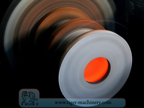
Центробежное литье
In centrifugal casting, a permanent mold is rotated continuously about its axis at high speeds (300 to 3000 rpm) as the molten metal is poured. The molten metal is centrifugally thrown towards the inside mold wall, where it solidifies after cooling. The casting is usually a fine-grained casting with a very fine-grained outer diameter, owing to chilling against the mould surface. Impurities and inclusions are thrown to the surface of the inside diameter, which can be machined away. Casting machines may be either horizontal or vertical-axis. Horizontal axis machines are preferred for long, thin cylinders, vertical machines for rings. Most castings are solidified from the outside first. This may be used to encourage directional solidification of the casting, and thus give useful metallurgical properties to it. Often the inner and outer layers are discarded and only the intermediary columnar zone is used. Centrifugal casting was the invention of Alfred Krupp, who used it to manufacture cast steel tyres for railway wheels in 1852.
Особенности центробежного литья
Отливки могут быть изготовлены практически любой длины, толщины и диаметра.
Из одной и той же формы можно производить детали с разной толщиной стенок.
Устраняет необходимость в сердечниках.
Устойчив к атмосферной коррозии, что типично для труб.
Механические свойства центробежных отливок отличные.
Только цилиндрические формы могут быть изготовлены с помощью этого процесса.
Ограничения по размеру составляют до 3 м (10 футов) в диаметре и 15 м (50 футов) в длину.
Толщина стенки от 2,5 мм до 125 мм (0,1 - 5,0 дюйма).
Допуск: по наружному диаметру может быть 2,5 мм (0,1 дюйма), по внутреннему диаметру может быть 3,8 мм (0,15 дюйма).
Обработка поверхности варьируется от 2,5 мм до 12,5 мм (0,1 - 0,5 дюйма) RMS.
Преимущества центробежного литья
Cylinders and shapes with rotational symmetry are most commonly cast by this technique. "Tall" castings (in the direction of the settling force acting, usually gravity) are always more difficult than short castings. In the centrifugal casting technique the radius of the rotation, along which the centrifugal force acts, replaces the vertical axis. The casting machine may be rotated to place this in any convenient orientation, relative to gravity's vertical. Horizontal and vertical axis machines are both used, simply to place the casting's longest dimension conveniently horizontal. Thin-walled cylinders are difficult to cast by other means, but centrifugal casting is particularly suited to them. To the rotation radius, these are effectively shallow flat castings and are thus simple. Centrifugal casting is also applied to the casting of disk and cylindrical shaped objects such as railway carriage wheels or machine fittings where the grain, flow, and balance are important to the durability and utility of the finished product. Providing that the shape is relatively constant in radius, noncircular shapes may also be cast.
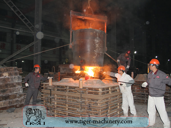
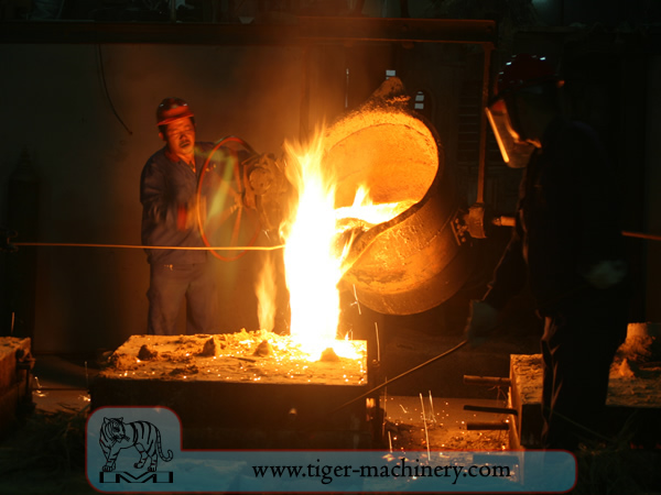
Песочное литье
Литье в песок, также известное как литье в песчаные формы, представляет собой процесс литья металла, характеризующийся использованием песка в качестве материала формы. Термин литье в песок может также относиться к объекту, произведенному с помощью этого процесса. Изделия из литья в песок производятся на специализированных заводах, называемых литейными цехами. Более 70% всех металлических отливок изготавливаются с помощью литья в песок.
Песчаное литье относительно дешево и достаточно огнеупорно даже для использования в сталелитейных цехах. В дополнение к песку, подходящее связующее вещество (обычно глина) смешивается или встречается с песком. Смесь увлажняется, как правило, водой, но иногда и другими веществами, для развития прочности и пластичности глины и придания агрегату пригодности для формовки. Песок обычно содержится в системе рам или формовочных ящиков, известных как опока. Полости формы и литниковая система создаются путем уплотнения песка вокруг моделей или шаблонов, либо вырезаются непосредственно в песке.
Модели песчаного литья
From the design, provided by an engineer or designer, a skilled pattern maker builds a pattern of the object to be produced, using wood, metal, or a plastic such as expanded polystyrene. Sand can be ground, swept or strickled into shape. The metal to be cast will contract during solidification, and this may be non-uniform due to uneven cooling. Therefore, the pattern must be slightly larger than the finished product, a difference known as contraction allowance. Pattern-makers are able to produce suitable patterns using Contraction rules (these are sometimes called shrink allowance rulers where the ruled markings are deliberately made to a larger spacing according to the percentage of extra length needed). Different scaled rules are used for different metals, because each metal and alloy contracts by an amount distinct from all others. Patterns also have core prints that create registers within the molds into which are placed sand cores. Such cores, sometimes reinforced by wires, are used to create under-cut profiles and cavities which cannot be molded with the cope and drag, such as the interior passages of valves or cooling passages in engine blocks.
Пути поступления металла в полость формы образуют литниковую систему и включают литниковую чашу, различные питатели, обеспечивающие хорошую подачу металла, и литниковые ходы, соединяющие литниковую систему с полостью отливки. Газы и пар, образующиеся при литье, выходят через проницаемый песок или через прибыли, которые добавляются либо в саму модель, либо в виде отдельных элементов.
Формовочный ящик и материалы для литья в песчаные формы
A multi-part molding box (known as a casting flask, the top and bottom halves of which are known respectively as the cope and drag) is prepared to receive the pattern. Molding boxes are made in segments that may be latched to each other and to end closures. For a simple object—flat on one side—the lower portion of the box, closed at the bottom, will be filled with a molding sand. The sand is packed in through a vibratory process called ramming, and in this case, periodically screeded level. The surface of the sand may then be stabilized with a sizing compound. The pattern is placed on the sand and another molding box segment is added. Additional sand is rammed over and around the pattern. Finally a cover is placed on the box and it is turned and unlatched, so that the halves of the mold may be parted and the pattern with its sprue and vent patterns removed. Additional sizing may be added and any defects introduced by the removal of the pattern are corrected. The box is closed again. This forms a green mold which must be dried to receive the hot metal. If the mold is not sufficiently dried a steam explosion can occur that can throw molten metal about. In some cases, the sand may be oiled instead of moistened, which makes possible casting without waiting for the sand to dry. Sand may also be bonded by chemical binders, such as furane resins or amine-hardened resins.
Холодное литье песка
Для контроля структуры затвердевания металла можно размещать в форме металлические пластины — холодильники. Связанное с этим быстрое локальное охлаждение формирует более мелкозернистую структуру и может привести к образованию несколько более твёрдого металла в этих местах. В чугунных отливках эффект аналогичен закалке металлов при ковке. Внутренний диаметр цилиндра двигателя делается твёрдым с помощью охлаждающего сердечника. В других металлах холодильники могут использоваться для стимулирования направленной кристаллизации отливки. Контролируя способ замерзания отливки, можно предотвратить образование внутренних пустот или пористости внутри отливок.
cores of sand casting
Для создания полостей в отливке — например, для жидкостного охлаждения в блоках двигателя и головках цилиндров — используются негативные формы для изготовления стержней. Обычно формованные из песка стержни вставляются в литейный ящик после удаления модели. По возможности проекты выполняются так, чтобы избежать использования стержней из-за дополнительного времени на настройку и, следовательно, большей стоимости.
При наличии готовой формы с соответствующей влажностью, ящик с песчаной формой затем устанавливается для заполнения расплавленным металлом — обычно это железо, сталь, бронза, латунь, алюминий, магниевые сплавы или различные сплавы цветных металлов, которые часто содержат свинец, олово и цинк. После заполнения жидким металлом ящик отставляют в сторону до тех пор, пока металл не остынет достаточно, чтобы стать прочным. Затем песок удаляют, обнажая грубую отливку, которая в случае железа или стали может ещё светиться красным. При литье таких металлов, как железо или свинец, которые значительно тяжелее литейного песка, литейную опоку часто накрывают тяжёлой плитой, чтобы предотвратить проблему, известную как всплытие формы. Всплытие формы происходит, когда давление металла деформирует песок над полостью формы, что приводит к браку отливки.
После литья стержни разрушаются стержнями или дробью и удаляются из отливки. Металл из литника и прибылей отрезается от черновой отливки. Могут применяться различные виды термической обработки для снятия напряжений после первичного охлаждения и повышения твердости — в случае стали или чугуна путем закалки в воде или масле. Отливка может быть дополнительно упрочнена поверхностной обработкой сжатием, например дробеструйной обработкой, которая повышает устойчивость к растягивающим трещинам и сглаживает шероховатую поверхность.
Требования к конструкции песчаного литья
The part to be made and its pattern must be designed to accommodate each stage of the process, as it must be possible to remove the pattern without disturbing the molding sand and to have proper locations to receive and position the cores. A slight taper, known as draft, must be used on surfaces perpendicular to the parting line, in order to be able to remove the pattern from the mold. This requirement also applies to cores, as they must be removed from the core box in which they are formed. The sprue and risers must be arranged to allow a proper flow of metal and gasses within the mold in order to avoid an incomplete casting. Should a piece of core or mold become dislodged it may be embedded in the final casting, forming a sand pit, which may render the casting unusable. Gas pockets can cause internal voids. These may be immediately visible or may only be revealed after extensive machining has been performed. For critical applications, or where the cost of wasted effort is a factor, non-destructive testing methods may be applied before further work is performed.
Вакуумная формовка
Vacuum molding (V-process) is a variation of the sand casting process for most ferrous and non-ferrous metals, in which unbonded sand is held in the flask with a vacuum. The pattern is specially vented so that a vacuum can be pulled through it. A heat-softened thin sheet (0.003 to 0.008 in (0.076 to 0.203 mm)) of plastic film is draped over the pattern and a vacuum is drawn (200 to 400 mmHg (27 to 53 kPa)). A special vacuum forming flask is placed over the plastic pattern and is filled with a free-flowing sand. The sand is vibrated to compact the sand and a sprue and pouring cup are formed in the cope. Another sheet of plastic is placed over the top of the sand in the flask and a vacuum is drawn through the special flask; this hardens and strengthens the unbonded sand. The vacuum is then released on the pattern and the cope is removed. The drag is made in the same way (without the sprue and pouring cup). Any cores are set in place and the mold is closed. The molten metal is poured while the cope and drag are still under a vacuum, because the plastic vaporizes but the vacuum keeps the shape of the sand while the metal solidifies. When the metal has solidified, the vacuum is turned off and the sand runs out freely, releasing the casting.
V-процесс известен тем, что не требует уклона, так как пластиковая пленка обладает определенной степенью смазывающей способности и слегка расширяется при создании вакуума в опоке. Процесс имеет высокую точность размеров с допуском ±0,010 дюйма на первый дюйм и ±0,002 дюйма на последующие. Возможны сечения размером до 0,090 дюйма (2,3 мм). Качество поверхности очень хорошее, обычно от 150 до 125 RMS. Другие преимущества включают отсутствие дефектов, связанных с влагой, отсутствие затрат на связующие, отличную проницаемость песка и отсутствие токсичных паров от сжигания связующих. Наконец, модель не изнашивается, так как песок не касается ее. Основной недостаток заключается в том, что процесс медленнее традиционного литья в песок, поэтому он подходит только для низких и средних объемов производства — примерно от 10 до 15 000 штук в год. Однако это делает его идеальным для прототипирования, так как модель легко модифицируется, поскольку она изготовлена из пластика.
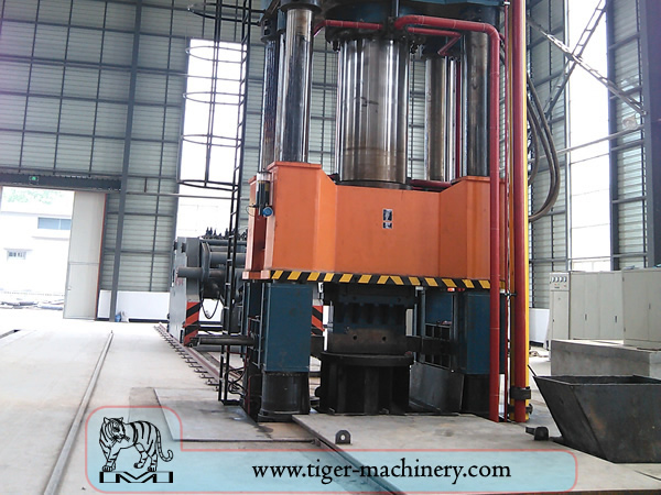
Ковка
Ковка — один из древнейших известных процессов обработки металлов. Традиционно ковка выполнялась кузнецом с помощью молота и наковальни, хотя внедрение водяной энергии в производство и обработку железа в XII веке привело молот и наковальню к устареванию. Кузница или горн развивались на протяжении веков, превратившись в предприятие с инженерными процессами, производственным оборудованием, оснасткой, сырьём и продукцией, отвечающими требованиям современной промышленности.
В современной промышленной ковке используются либо прессы, либо молоты, работающие от сжатого воздуха, электричества, гидравлики или пара. Эти молоты могут иметь возвратно-поступательные массы в тысячи фунтов. Меньшие силовые молоты с возвратно-поступательной массой 500 фунтов (230 кг) или менее, а также гидравлические прессы распространены и в художественных кузницах. Некоторые паровые молоты всё ещё используются, но они устарели с появлением других, более удобных источников энергии.
Преимущества и недостатки ковки
Ковка позволяет получить деталь, которая прочнее, чем эквивалентная литая или механически обработанная деталь. По мере придания металлу формы в процессе ковки его внутреннее зерно деформируется, следуя общей форме детали. В результате зерно остается непрерывным по всей детали, что придает ей улучшенные прочностные характеристики.
Некоторые металлы можно ковать холодным способом, но железо и сталь почти всегда куют горячим. Горячая ковка предотвращает наклеп, который возник бы при холодной ковке и усложнил бы последующую механическую обработку детали. Кроме того, хотя в некоторых случаях наклеп может быть желателен, другие методы упрочнения, такие как термообработка, обычно более экономичны и управляемы. Сплавы, подверженные дисперсионному твердению, например большинство алюминиевых сплавов и титан, можно ковать горячим способом с последующим упрочнением.
Производственная ковка требует значительных капитальных вложений в оборудование, оснастку, производственные помещения и персонал. В случае горячей ковки необходима высокотемпературная печь (иногда называемая горном) для нагрева слитков или заготовок. Из-за массивности крупных ковочных молотов и прессов, а также деталей, которые они могут производить, а также опасностей, присущих работе с горячим металлом, часто требуется специальное здание для размещения операции. В случае ковки в штампах необходимо предусмотреть меры для поглощения ударов и вибрации, создаваемых молотом. Большинство ковочных операций используют штампы для формовки металла, которые должны быть точно обработаны и тщательно термообработаны для правильного формирования заготовки, а также для выдерживания огромных сил, возникающих в процессе.
Процессы ковки
Существует множество различных видов процессов ковки, однако их можно разделить на три основных класса:
Вытянутый: длина увеличивается, поперечное сечение уменьшается
Upset: длина уменьшается, поперечное сечение увеличивается
Сжатие в закрытых штампах: создает многонаправленный поток.
Обычные процессы ковки включают: вальцовку, ротационную ковку, осадку, свободную ковку, штамповку в открытых штампах, штамповку в закрытых штампах, прессовую ковку, автоматическую горячую ковку и высадку.