Casting technology
We can offer the centrifugal casting, sand casting, vacuum molding casting and forging technology parts with well and fine machinings for strict requirements.
Centrifugal casting
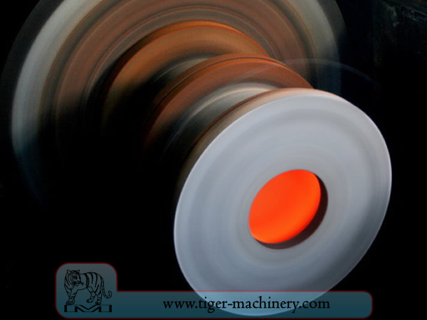
In centrifugal casting, a permanent mold is rotated continuously about its axis at high speeds (300 to 3000 rpm) as the molten metal is poured. The molten metal is centrifugally thrown towards the inside mold wall, where it solidifies after cooling. The casting is usually a fine-grained casting with a very fine-grained outer diameter, owing to chilling against the mould surface. Impurities and inclusions are thrown to the surface of the inside diameter, which can be machined away. Casting machines may be either horizontal or vertical-axis. Horizontal axis machines are preferred for long, thin cylinders, vertical machines for rings. Most castings are solidified from the outside first. This may be used to encourage directional solidification of the casting, and thus give useful metallurgical properties to it. Often the inner and outer layers are discarded and only the intermediary columnar zone is used. Centrifugal casting was the invention of Alfred Krupp, who used it to manufacture cast steel tyres for railway wheels in 1852.
Features of centrifugal casting
Castings can be made in almost any length, thickness and diameter.
Different wall thicknesses can be produced from the same size mold.
Eliminates the need for cores.
Resistant to atmospheric corrosion, a typical situation with pipes.
Mechanical properties of centrifugal castings are excellent.
Only cylindrical shapes can be produced with this process.
Size limits are up to 3 m (10 feet) diameter and 15 m (50 feet) length.
Wall thickness range from 2.5 mm to 125 mm (0.1 - 5.0 in).
Tolerance limit: on the OD can be 2.5 mm (0.1 in) on the ID can be 3.8 mm (0.15 in).
Surface finish ranges from 2.5 mm to 12.5 mm (0.1 - 0.5 in) rms.
Benefits of centrifugal casting
Cylinders and shapes with rotational symmetry are most commonly cast by this technique. "Tall" castings (in the direction of the settling force acting, usually gravity) are always more difficult than short castings. In the centrifugal casting technique the radius of the rotation, along which the centrifugal force acts, replaces the vertical axis. The casting machine may be rotated to place this in any convenient orientation, relative to gravity's vertical. Horizontal and vertical axis machines are both used, simply to place the casting's longest dimension conveniently horizontal. Thin-walled cylinders are difficult to cast by other means, but centrifugal casting is particularly suited to them. To the rotation radius, these are effectively shallow flat castings and are thus simple. Centrifugal casting is also applied to the casting of disk and cylindrical shaped objects such as railway carriage wheels or machine fittings where the grain, flow, and balance are important to the durability and utility of the finished product. Providing that the shape is relatively constant in radius, noncircular shapes may also be cast.
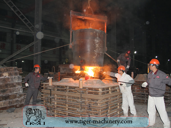
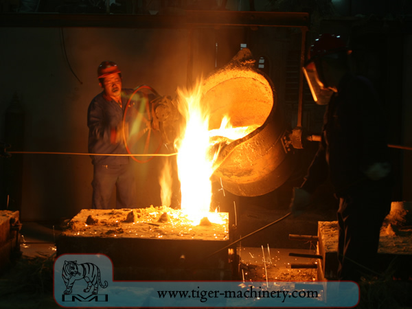
Sand casting
Sand casting, also known as sand molded casting, is a metal casting process characterized by using sand as the mold material. The term sand casting can also refer to an object produced via the sand casting process. Sand castings are produced in specialized factories called foundries. Over 70% of all metal castings are produced via a sand casting process.
Sand casting is relatively cheap and sufficiently refractory even for steel foundry use. In addition to the sand, a suitable bonding agent (usually clay) is mixed or occurs with the sand. The mixture is moistened, typically with water, but sometimes with other substances, to develop strength and plasticity of the clay and to make the aggregate suitable for molding. The sand is typically contained in a system of frames or mold boxes known as a flask. The mold cavities and gate system are created by compacting the sand around models, or patterns, or carved directly into the sand.
Patterns of sand casting
From the design, provided by an engineer or designer, a skilled pattern maker builds a pattern of the object to be produced, using wood, metal, or a plastic such as expanded polystyrene. Sand can be ground, swept or strickled into shape. The metal to be cast will contract during solidification, and this may be non-uniform due to uneven cooling. Therefore, the pattern must be slightly larger than the finished product, a difference known as contraction allowance. Pattern-makers are able to produce suitable patterns using Contraction rules (these are sometimes called shrink allowance rulers where the ruled markings are deliberately made to a larger spacing according to the percentage of extra length needed). Different scaled rules are used for different metals, because each metal and alloy contracts by an amount distinct from all others. Patterns also have core prints that create registers within the molds into which are placed sand cores. Such cores, sometimes reinforced by wires, are used to create under-cut profiles and cavities which cannot be molded with the cope and drag, such as the interior passages of valves or cooling passages in engine blocks.
Paths for the entrance of metal into the mold cavity constitute the runner system and include the sprue, various feeders which maintain a good metal 'feed', and in-gates which attach the runner system to the casting cavity. Gas and steam generated during casting exit through the permeable sand or via risers, which are added either in the pattern itself, or as separate pieces.
Molding box and materials of sand casting
A multi-part molding box (known as a casting flask, the top and bottom halves of which are known respectively as the cope and drag) is prepared to receive the pattern. Molding boxes are made in segments that may be latched to each other and to end closures. For a simple object—flat on one side—the lower portion of the box, closed at the bottom, will be filled with a molding sand. The sand is packed in through a vibratory process called ramming, and in this case, periodically screeded level. The surface of the sand may then be stabilized with a sizing compound. The pattern is placed on the sand and another molding box segment is added. Additional sand is rammed over and around the pattern. Finally a cover is placed on the box and it is turned and unlatched, so that the halves of the mold may be parted and the pattern with its sprue and vent patterns removed. Additional sizing may be added and any defects introduced by the removal of the pattern are corrected. The box is closed again. This forms a green mold which must be dried to receive the hot metal. If the mold is not sufficiently dried a steam explosion can occur that can throw molten metal about. In some cases, the sand may be oiled instead of moistened, which makes possible casting without waiting for the sand to dry. Sand may also be bonded by chemical binders, such as furane resins or amine-hardened resins.
Chills of sand casting
To control the solidification structure of the metal, it is possible to place metal plates, chills, in the mold. The associated rapid local cooling will form a finer-grained structure and may form a somewhat harder metal at these locations. In ferrous castings, the effect is similar to quenching metals in forge work. The inner diameter of an engine cylinder is made hard by a chilling core. In other metals, chills may be used to promote directional solidification of the casting. In controlling the way a casting freezes, it is possible to prevent internal voids or porosity inside castings.
Cores of sand casting
To produce cavities within the casting—such as for liquid cooling in engine blocks and cylinder heads—negative forms are used to produce cores. Usually sand-molded, cores are inserted into the casting box after removal of the pattern. Whenever possible, designs are made that avoid the use of cores, due to the additional set-up time and thus greater cost.
With a completed mold at the appropriate moisture content, the box containing the sand mold is then positioned for filling with molten metal—typically iron, steel, bronze, brass, aluminium, magnesium alloys, or various pot metal alloys, which often include lead, tin, and zinc. After filling with liquid metal the box is set aside until the metal is sufficiently cool to be strong. The sand is then removed revealing a rough casting that, in the case of iron or steel, may still be glowing red. When casting with metals like iron or lead, which are significantly heavier than the casting sand, the casting flask is often covered with a heavy plate to prevent a problem known as floating the mold. Floating the mold occurs when the pressure of the metal pushes the sand above the mold cavity out of shape, causing the casting to fail.
After casting, the cores are broken up by rods or shot and removed from the casting. The metal from the sprue and risers is cut from the rough casting. Various heat treatments may be applied to relieve stresses from the initial cooling and to add hardness—in the case of steel or iron, by quenching in water or oil. The casting may be further strengthened by surface compression treatment—like shot peening—that adds resistance to tensile cracking and smooths the rough surface.
Design requirements of sand casting
The part to be made and its pattern must be designed to accommodate each stage of the process, as it must be possible to remove the pattern without disturbing the molding sand and to have proper locations to receive and position the cores. A slight taper, known as draft, must be used on surfaces perpendicular to the parting line, in order to be able to remove the pattern from the mold. This requirement also applies to cores, as they must be removed from the core box in which they are formed. The sprue and risers must be arranged to allow a proper flow of metal and gasses within the mold in order to avoid an incomplete casting. Should a piece of core or mold become dislodged it may be embedded in the final casting, forming a sand pit, which may render the casting unusable. Gas pockets can cause internal voids. These may be immediately visible or may only be revealed after extensive machining has been performed. For critical applications, or where the cost of wasted effort is a factor, non-destructive testing methods may be applied before further work is performed.
Vacuum molding casting
Vacuum molding (V-process) is a variation of the sand casting process for most ferrous and non-ferrous metals, in which unbonded sand is held in the flask with a vacuum. The pattern is specially vented so that a vacuum can be pulled through it. A heat-softened thin sheet (0.003 to 0.008 in (0.076 to 0.203 mm)) of plastic film is draped over the pattern and a vacuum is drawn (200 to 400 mmHg (27 to 53 kPa)). A special vacuum forming flask is placed over the plastic pattern and is filled with a free-flowing sand. The sand is vibrated to compact the sand and a sprue and pouring cup are formed in the cope. Another sheet of plastic is placed over the top of the sand in the flask and a vacuum is drawn through the special flask; this hardens and strengthens the unbonded sand. The vacuum is then released on the pattern and the cope is removed. The drag is made in the same way (without the sprue and pouring cup). Any cores are set in place and the mold is closed. The molten metal is poured while the cope and drag are still under a vacuum, because the plastic vaporizes but the vacuum keeps the shape of the sand while the metal solidifies. When the metal has solidified, the vacuum is turned off and the sand runs out freely, releasing the casting.
The V-process is known for not requiring a draft because the plastic film has a certain degree of lubricity and it expands slightly when the vacuum is drawn in the flask. The process has high dimensional accuracy, with a tolerance of ±0.010 in for the first inch and ±0.002 in there after. Cross-sections as small as 0.090 in (2.3 mm) are possible. The surface finish is very good, usually between 150 to 125 rms. Other advantages include no moisture related defects, no cost for binders, excellent sand permeability, and no toxic fumes from burning the binders. Finally, the pattern does not wear out because the sand does not touch it. The main disadvantage is that the process is slower than traditional sand casting so it is only suitable for low to medium production volumes; approximately 10 to 15,000 pieces a year. However, this makes it perfect for prototype work, because the pattern can be easily modified as it is made from plastic.
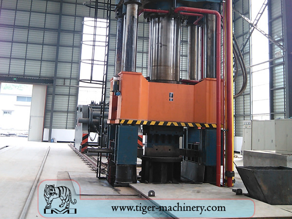
Forging
Forging is one of the oldest known metalworking processes. Traditionally, forging was performed by a smith using hammer and anvil, though introducing water power to the production and working of iron in the 12th century drove the hammer and anvil into obsolescence. The smithy or forge has evolved over centuries to become a facility with engineered processes, production equipment, tooling, raw materials and products to meet the demands of modern industry.
In modern times, industrial forging is done either with presses or with hammers powered by compressed air, electricity, hydraulics or steam. These hammers may have reciprocating weights in the thousands of pounds. Smaller power hammers, 500 lb (230 kg) or less reciprocating weight, and hydraulic presses are common in art smithies as well. Some steam hammers remain in use, but they became obsolete with the availability of the other, more convenient, power sources.
Advantages and disadvantages of forging
Forging can produce a piece that is stronger than an equivalent cast or machined part. As the metal is shaped during the forging process, its internal grain deforms to follow the general shape of the part. As a result, the grain is continuous throughout the part, giving rise to a piece with improved strength characteristics.
Some metals may be forged cold, but iron and steel are almost always hot forged. Hot forging prevents the work hardening that would result from cold forging, which would increase the difficulty of performing secondary machining operations on the piece. Also, while work hardening may be desirable in some circumstances, other methods of hardening the piece, such as heat treating, are generally more economical and more controllable. Alloys that are amenable to precipitation hardening, such as most aluminium alloys and titanium, can be hot forged, followed by hardening.
Production forging involves significant capital expenditure for machinery, tooling, facilities and personnel. In the case of hot forging, a high-temperature furnace (sometimes referred to as the forge) is required to heat ingots or billets. Owing to the massiveness of large forging hammers and presses and the parts they can produce, as well as the dangers inherent in working with hot metal, a special building is frequently required to house the operation. In the case of drop forging operations, provisions must be made to absorb the shock and vibration generated by the hammer. Most forging operations use metal-forming dies, which must be precisely machined and carefully heat-treated to correctly shape the workpiece, as well as to withstand the tremendous forces involved.
Processes of forging
There are many different kinds of forging processes available, however they can be grouped into three main classes:
Drawn out: length increases, cross-section decreases
Upset: length decreases, cross-section increases
Squeezed in closed compression dies: produces multidirectional flow
Common forging processes include: roll forging, swaging, cogging, open-die forging, impression-die forging, press forging, automatic hot forging and upsetting.