تكنولوجيا الصب
يمكننا تقديم أجزاء الصب بالطرد المركزي، الصب الرملي، الصب بالقالب الفراغي، وأجزاء التشكيل بالطرق مع تشغيل آلي جيد ودقيق لتلبية المتطلبات الصارمة.
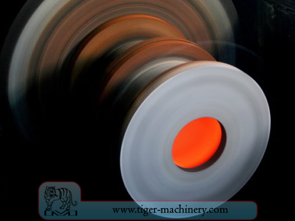
صب بالطرد المركزي
In centrifugal casting, a permanent mold is rotated continuously about its axis at high speeds (300 to 3000 rpm) as the molten metal is poured. The molten metal is centrifugally thrown towards the inside mold wall, where it solidifies after cooling. The casting is usually a fine-grained casting with a very fine-grained outer diameter, owing to chilling against the mould surface. Impurities and inclusions are thrown to the surface of the inside diameter, which can be machined away. Casting machines may be either horizontal or vertical-axis. Horizontal axis machines are preferred for long, thin cylinders, vertical machines for rings. Most castings are solidified from the outside first. This may be used to encourage directional solidification of the casting, and thus give useful metallurgical properties to it. Often the inner and outer layers are discarded and only the intermediary columnar zone is used. Centrifugal casting was the invention of Alfred Krupp, who used it to manufacture cast steel tyres for railway wheels in 1852.
ميزات الصب بالطرد المركزي
يمكن تصنيع المسبوكات بأي طول وسمك وقطر تقريبًا.
يمكن إنتاج سماكات جدار مختلفة من نفس القالب بنفس الحجم.
يلغي الحاجة إلى النوى.
مقاوم للتآكل الجوي، وهو حالة نموذجية للأنابيب.
الخصائص الميكانيكية للمسبوكات الطاردة المركزية ممتازة.
يمكن إنتاج الأشكال الأسطوانية فقط باستخدام هذه العملية.
حدود الحجم تصل إلى 3 أمتار (10 أقدام) في القطر و15 مترًا (50 قدمًا) في الطول.
يتراوح سمك الجدار من 2.5 مم إلى 125 مم (0.1 - 5.0 بوصة).
حد التسامح: على القطر الخارجي يمكن أن يكون 2.5 مم (0.1 بوصة) وعلى القطر الداخلي يمكن أن يكون 3.8 مم (0.15 بوصة).
يتراوح تشطيب السطح من 2.5 مم إلى 12.5 مم (0.1 - 0.5 بوصة) rms.
فوائد الصب بالطرد المركزي
Cylinders and shapes with rotational symmetry are most commonly cast by this technique. "Tall" castings (in the direction of the settling force acting, usually gravity) are always more difficult than short castings. In the centrifugal casting technique the radius of the rotation, along which the centrifugal force acts, replaces the vertical axis. The casting machine may be rotated to place this in any convenient orientation, relative to gravity's vertical. Horizontal and vertical axis machines are both used, simply to place the casting's longest dimension conveniently horizontal. Thin-walled cylinders are difficult to cast by other means, but centrifugal casting is particularly suited to them. To the rotation radius, these are effectively shallow flat castings and are thus simple. Centrifugal casting is also applied to the casting of disk and cylindrical shaped objects such as railway carriage wheels or machine fittings where the grain, flow, and balance are important to the durability and utility of the finished product. Providing that the shape is relatively constant in radius, noncircular shapes may also be cast.
السبك بالرمل
السباكة الرملية، المعروفة أيضًا باسم الصب في القوالب الرملية، هي عملية صب المعادن تتميز باستخدام الرمل كمادة للقالب. يمكن أن يشير مصطلح السباكة الرملية أيضًا إلى جسم يتم إنتاجه عبر عملية السباكة الرملية. يتم إنتاج المسبوكات الرملية في مصانع متخصصة تسمى المسابك. يتم إنتاج أكثر من 70% من جميع المسبوكات المعدنية عبر عملية السباكة الرملية.
السباكة الرملية رخيصة نسبيًا ومقاومة للحرارة بشكل كافٍ حتى لاستخدامها في مسابك الفولاذ. بالإضافة إلى الرمل، يتم خلط مادة رابطة مناسبة (عادةً الطين) أو تتواجد مع الرمل. يتم ترطيب الخليط، عادةً بالماء، وأحيانًا بمواد أخرى، لتطوير قوة ومرونة الطين وجعل المادة الإجمالية مناسبة للتشكيل. يُحتوى الرمل عادةً في نظام من الإطارات أو صناديق القوالب المعروفة باسم القارورة. يتم إنشاء تجاويف القالب ونظام البوابات عن طريق ضغط الرمل حول النماذج أو القوالب، أو نحتها مباشرة في الرمل.
أنماط الصب بالرمل
From the design, provided by an engineer or designer, a skilled pattern maker builds a pattern of the object to be produced, using wood, metal, or a plastic such as expanded polystyrene. Sand can be ground, swept or strickled into shape. The metal to be cast will contract during solidification, and this may be non-uniform due to uneven cooling. Therefore, the pattern must be slightly larger than the finished product, a difference known as contraction allowance. Pattern-makers are able to produce suitable patterns using Contraction rules (these are sometimes called shrink allowance rulers where the ruled markings are deliberately made to a larger spacing according to the percentage of extra length needed). Different scaled rules are used for different metals, because each metal and alloy contracts by an amount distinct from all others. Patterns also have core prints that create registers within the molds into which are placed sand cores. Such cores, sometimes reinforced by wires, are used to create under-cut profiles and cavities which cannot be molded with the cope and drag, such as the interior passages of valves or cooling passages in engine blocks.
مسارات دخول المعدن إلى تجويف القالب تشكل نظام الجريان وتشمل المغذي الرئيسي، ومغذيات مختلفة تحافظ على تغذية جيدة للمعدن، ومداخل تربط نظام الجريان بتجويف الصب. الغاز والبخار المتولدان أثناء الصب يخرجان عبر الرمل المسامي أو عبر قوائم التهوية، التي تُضاف إما في النموذج نفسه أو كقطع منفصلة.
قالب الصب والمواد المستخدمة في الصب بالرمل
A multi-part molding box (known as a casting flask, the top and bottom halves of which are known respectively as the cope and drag) is prepared to receive the pattern. Molding boxes are made in segments that may be latched to each other and to end closures. For a simple object—flat on one side—the lower portion of the box, closed at the bottom, will be filled with a molding sand. The sand is packed in through a vibratory process called ramming, and in this case, periodically screeded level. The surface of the sand may then be stabilized with a sizing compound. The pattern is placed on the sand and another molding box segment is added. Additional sand is rammed over and around the pattern. Finally a cover is placed on the box and it is turned and unlatched, so that the halves of the mold may be parted and the pattern with its sprue and vent patterns removed. Additional sizing may be added and any defects introduced by the removal of the pattern are corrected. The box is closed again. This forms a green mold which must be dried to receive the hot metal. If the mold is not sufficiently dried a steam explosion can occur that can throw molten metal about. In some cases, the sand may be oiled instead of moistened, which makes possible casting without waiting for the sand to dry. Sand may also be bonded by chemical binders, such as furane resins or amine-hardened resins.
تشيلز من الصب الرملي
للتحكم في بنية تصلب المعدن، يمكن وضع ألواح معدنية (مبردات) في القالب، حيث يؤدي التبريد السريع الموضعي إلى تكوين بنية حبيبية أدق وقد يشكل معدنًا أكثر صلابة في تلك المواقع. في المسبوكات الحديدية، يشبه التأثير عملية التبريد السريع في أعمال الحدادة. يتم جعل القطر الداخلي لأسطوانة المحرك صلبًا باستخدام قلب تبريد. في المعادن الأخرى، يمكن استخدام المبردات لتعزيز التصلب الاتجاهي للمسبوكات، ومن خلال التحكم في طريقة تجمد المسبوكات، يمكن منع الفراغات الداخلية أو المسامية داخل المسبوكات.
قلوب الصب الرملي
لإنتاج تجاويف داخل المسبوكات—مثل التبريد السائل في كتل المحرك ورؤوس الأسطوانات—تُستخدم أشكال سالبة لإنتاج القلوب. عادةً ما تكون القلوب مصبوبة بالرمل، وتُدخل في صندوق الصب بعد إزالة النموذج. كلما أمكن، تُصمم التصاميم لتجنب استخدام القلوب، بسبب وقت الإعداد الإضافي وبالتالي التكلفة الأعلى.
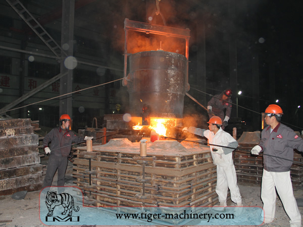
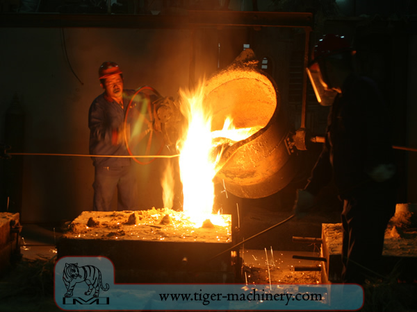
بعد الانتهاء من القالب بالرطوبة المناسبة، يتم وضع الصندوق الذي يحتوي على قالب الرمل لملئه بالمعدن المنصهر—عادةً الحديد، الفولاذ، البرونز، النحاس الأصفر، الألومنيوم، سبائك المغنيسيوم، أو سبائك معادن مختلفة غالبًا ما تحتوي على الرصاص والقصدير والزنك. بعد الملء بالمعدن السائل، يُترك الصندوق جانبًا حتى يبرد المعدن بدرجة كافية ليكون قويًا. ثم يُزال الرمل ليكشف عن صب خام، وفي حالة الحديد أو الفولاذ، قد يظل متوهجًا باللون الأحمر. عند الصب بمعادن مثل الحديد أو الرصاص، التي تكون أثقل بكثير من رمل الصب، غالبًا ما يُغطى إطار الصب بلوحة ثقيلة لمنع مشكلة تُعرف بـ"طفو القالب". يحدث طفو القالب عندما يدفع ضغط المعدن الرمل فوق تجويف القالب خارج شكله، مما يؤدي إلى فشل الصب.
بعد الصب، يتم تفتيت القوالب الداخلية باستخدام قضبان أو طلقات معدنية وإزالتها من المسبوكة. يتم قطع المعدن من مجرى الصب والمصاعد من المسبوكة الخام. قد تُطبق معالجات حرارية مختلفة لتخفيف الإجهادات الناتجة عن التبريد الأولي ولزيادة الصلابة—في حالة الفولاذ أو الحديد، عن طريق التبريد السريع في الماء أو الزيت. يمكن تعزيز المسبوكة بشكل أكبر من خلال معالجة الضغط السطحي—مثل طرق السفع بالخرز—التي تضيف مقاومة للتشقق الشد وتنعيم السطح الخشن.
متطلبات تصميم صب الرمل
The part to be made and its pattern must be designed to accommodate each stage of the process, as it must be possible to remove the pattern without disturbing the molding sand and to have proper locations to receive and position the cores. A slight taper, known as draft, must be used on surfaces perpendicular to the parting line, in order to be able to remove the pattern from the mold. This requirement also applies to cores, as they must be removed from the core box in which they are formed. The sprue and risers must be arranged to allow a proper flow of metal and gasses within the mold in order to avoid an incomplete casting. Should a piece of core or mold become dislodged it may be embedded in the final casting, forming a sand pit, which may render the casting unusable. Gas pockets can cause internal voids. These may be immediately visible or may only be revealed after extensive machining has been performed. For critical applications, or where the cost of wasted effort is a factor, non-destructive testing methods may be applied before further work is performed.
صب القوالب بالفراغ
Vacuum molding (V-process) is a variation of the sand casting process for most ferrous and non-ferrous metals, in which unbonded sand is held in the flask with a vacuum. The pattern is specially vented so that a vacuum can be pulled through it. A heat-softened thin sheet (0.003 to 0.008 in (0.076 to 0.203 mm)) of plastic film is draped over the pattern and a vacuum is drawn (200 to 400 mmHg (27 to 53 kPa)). A special vacuum forming flask is placed over the plastic pattern and is filled with a free-flowing sand. The sand is vibrated to compact the sand and a sprue and pouring cup are formed in the cope. Another sheet of plastic is placed over the top of the sand in the flask and a vacuum is drawn through the special flask; this hardens and strengthens the unbonded sand. The vacuum is then released on the pattern and the cope is removed. The drag is made in the same way (without the sprue and pouring cup). Any cores are set in place and the mold is closed. The molten metal is poured while the cope and drag are still under a vacuum, because the plastic vaporizes but the vacuum keeps the shape of the sand while the metal solidifies. When the metal has solidified, the vacuum is turned off and the sand runs out freely, releasing the casting.
تتميز عملية V بعدم الحاجة إلى زاوية سحب لأن الفيلم البلاستيكي يتمتع بدرجة معينة من التزليق ويتوسع قليلاً عند سحب الفراغ في القالب. تتمتع العملية بدقة أبعاد عالية، مع تفاوت ±0.010 بوصة للبوصة الأولى و±0.002 بوصة بعد ذلك. يمكن تحقيق مقاطع عرضية صغيرة تصل إلى 0.090 بوصة (2.3 مم). تشطيب السطح جيد جداً، عادةً بين 150 و125 RMS. تشمل المزايا الأخرى عدم وجود عيوب مرتبطة بالرطوبة، وعدم تكلفة للمواد الرابطة، ونفاذية ممتازة للرمل، وعدم وجود أبخرة سامة من حرق المواد الرابطة. أخيراً، لا يتآكل النموذج لأن الرمل لا يلمسه. العيب الرئيسي هو أن العملية أبطأ من الصب بالرمل التقليدي، لذا فهي مناسبة فقط لأحجام الإنتاج المنخفضة إلى المتوسطة؛ حوالي 10 إلى 15,000 قطعة سنوياً. ومع ذلك، فإن هذا يجعلها مثالية لأعمال النماذج الأولية، لأنه يمكن تعديل النموذج بسهولة لأنه مصنوع من البلاستيك.
تزوير
الطرق هو أحد أقدم عمليات تشغيل المعادن المعروفة. تقليديًا، كان الطرق يُؤدى بواسطة حداد باستخدام مطرقة وسندان، لكن إدخال الطاقة المائية في إنتاج ومعالجة الحديد في القرن الثاني عشر دفع المطرقة والسندان إلى الاندثار. تطورت الحدادة أو المسبك على مر القرون لتصبح منشأة ذات عمليات هندسية، ومعدات إنتاج، وأدوات، ومواد خام، ومنتجات تلبي متطلبات الصناعة الحديثة.
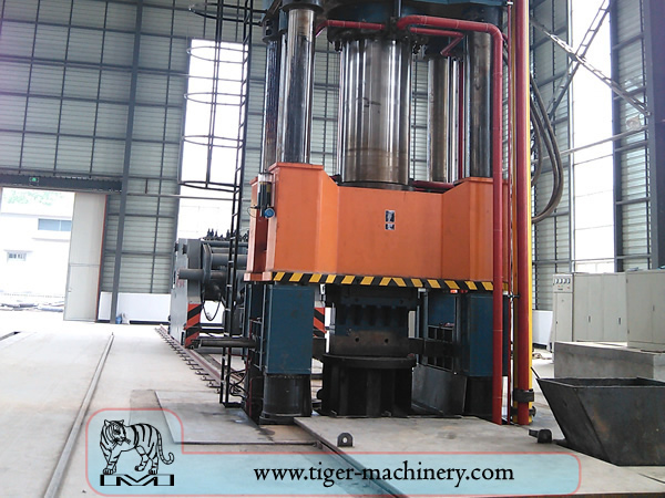
في العصر الحديث، يتم إجراء التشكيل الصناعي إما باستخدام المكابس أو المطارق التي تعمل بالهواء المضغوط أو الكهرباء أو الهيدروليكا أو البخار. قد تحتوي هذه المطارق على أوزان متحركة تصل إلى آلاف الأرطال. كما أن المطارق الكهربائية الصغيرة التي يقل وزنها المتحرك عن 500 رطل (230 كجم) والمكابس الهيدروليكية شائعة في ورش الحدادة الفنية أيضًا. لا تزال بعض المطارق البخارية قيد الاستخدام، لكنها أصبحت قديمة مع توفر مصادر الطاقة الأخرى الأكثر ملاءمة.
مزايا وعيوب التشكيل بالطرق
يمكن أن ينتج التشكيل قطعة أقوى من القطعة المكافئة المصبوبة أو المشغولة آليًا. عندما يتشكل المعدن أثناء عملية التشكيل، يتشوه هيكله الحبيبي الداخلي ليتبع الشكل العام للقطعة. ونتيجة لذلك، يكون الحبيبي مستمرًا في جميع أنحاء القطعة، مما يؤدي إلى قطعة ذات خصائص قوة محسنة.
يمكن تشكيل بعض المعادن بالطرق على البارد، لكن الحديد والصلب يُطرقان دائمًا على الساخن. يمنع الطرق على الساخن التصلد الناتج عن الطرق على البارد، مما يزيد صعوبة عمليات التشغيل الثانوية على القطعة. أيضًا، بينما قد يكون التصلد مرغوبًا في بعض الظروف، فإن طرق تصلب القطعة الأخرى مثل المعالجة الحرارية تكون عمومًا أكثر اقتصادية وأكثر قابلية للتحكم. السبائك القابلة للتصلد بالترسيب، مثل معظم سبائك الألومنيوم والتيتانيوم، يمكن طرقها على الساخن ثم تصلبها.
ينطوي إنتاج التشكيل على نفقات رأسمالية كبيرة للآلات، القوالب، المرافق والعمالة. في حالة التشكيل الساخن، يلزم فرن عالي الحرارة (يُشار إليه أحيانًا باسم المطرقة) لتسخين السبائك أو القضبان. نظرًا لضخامة المطارق والمكابس الكبيرة للتشكيل والأجزاء التي يمكنها إنتاجها، بالإضافة إلى المخاطر الكامنة في العمل مع المعدن الساخن، غالبًا ما يلزم بناء خاص لإيواء العملية. في حالة عمليات التشكيل بالطرق، يجب توفير ترتيبات لامتصاص الصدمات والاهتزازات الناتجة عن المطرقة. تستخدم معظم عمليات التشكيل قوالب تشكيل معدنية، والتي يجب تشغيلها بدقة ومعالجتها حرارياً بعناية لتشكيل قطعة العمل بشكل صحيح، وكذلك لتحمل القوى الهائلة المتضمنة.
عمليات الحدادة
هناك العديد من أنواع عمليات التشكيل المختلفة المتاحة، ومع ذلك يمكن تصنيفها إلى ثلاث فئات رئيسية:
مسحوب: يزداد الطول، ويقل المقطع العرضي
الانزعاج: يقل الطول، تزداد مساحة المقطع العرضي
مكبوس في قوالب ضغط مغلقة: ينتج تدفقًا متعدد الاتجاهات
عمليات التشكيل بالطرق الشائعة تشمل: الطرق بالدرفلة، الطرق بالتصغير، الطرق بالتشكيل المفتوح، الطرق بالقالب المطبوع، الطرق بالضغط، الطرق الساخن الآلي، والطرق بالرفع.