Technologia odlewania
Możemy zaoferować części wykonane technologią odlewania odśrodkowego, odlewania piaskowego, odlewania próżniowego i kucia, z precyzyjną obróbką spełniającą rygorystyczne wymagania.
Odlew odśrodkowy
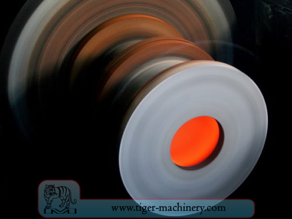
In centrifugal casting, a permanent mold is rotated continuously about its axis at high speeds (300 to 3000 rpm) as the molten metal is poured. The molten metal is centrifugally thrown towards the inside mold wall, where it solidifies after cooling. The casting is usually a fine-grained casting with a very fine-grained outer diameter, owing to chilling against the mould surface. Impurities and inclusions are thrown to the surface of the inside diameter, which can be machined away. Casting machines may be either horizontal or vertical-axis. Horizontal axis machines are preferred for long, thin cylinders, vertical machines for rings. Most castings are solidified from the outside first. This may be used to encourage directional solidification of the casting, and thus give useful metallurgical properties to it. Often the inner and outer layers are discarded and only the intermediary columnar zone is used. Centrifugal casting was the invention of Alfred Krupp, who used it to manufacture cast steel tyres for railway wheels in 1852.
Cechy odlewania odśrodkowego
Odlewy mogą być wykonane w prawie każdej długości, grubości i średnicy.
Z tej samej formy można produkować różne grubości ścianek.
Eliminuje potrzebę stosowania rdzeni.
Odporny na korozję atmosferyczną, typową sytuację dla rur.
Właściwości mechaniczne odlewów odśrodkowych są doskonałe.
Tylko cylindryczne kształty mogą być wytwarzane za pomocą tego procesu.
Ograniczenia rozmiarów wynoszą do 3 m (10 stóp) średnicy i 15 m (50 stóp) długości.
Grubość ścianki wynosi od 2,5 mm do 125 mm (0,1 - 5,0 cala).
Tolerancja: na średnicy zewnętrznej może wynosić 2,5 mm (0,1 cala), na średnicy wewnętrznej może wynosić 3,8 mm (0,15 cala).
Wykończenie powierzchni wynosi od 2,5 mm do 12,5 mm (0,1 - 0,5 cala) rms.
Zalety odlewania odśrodkowego
Cylinders and shapes with rotational symmetry are most commonly cast by this technique. "Tall" castings (in the direction of the settling force acting, usually gravity) are always more difficult than short castings. In the centrifugal casting technique the radius of the rotation, along which the centrifugal force acts, replaces the vertical axis. The casting machine may be rotated to place this in any convenient orientation, relative to gravity's vertical. Horizontal and vertical axis machines are both used, simply to place the casting's longest dimension conveniently horizontal. Thin-walled cylinders are difficult to cast by other means, but centrifugal casting is particularly suited to them. To the rotation radius, these are effectively shallow flat castings and are thus simple. Centrifugal casting is also applied to the casting of disk and cylindrical shaped objects such as railway carriage wheels or machine fittings where the grain, flow, and balance are important to the durability and utility of the finished product. Providing that the shape is relatively constant in radius, noncircular shapes may also be cast.
Odlewanie piaskowe
Odlewanie piaskowe, znane również jako odlewanie w formach piaskowych, to proces odlewania metali charakteryzujący się użyciem piasku jako materiału formy. Termin odlewanie piaskowe może również odnosić się do przedmiotu wytworzonego w procesie odlewania piaskowego. Odlewy piaskowe są produkowane w wyspecjalizowanych fabrykach zwanych odlewniami. Ponad 70% wszystkich odlewów metalowych jest wytwarzanych w procesie odlewania piaskowego.
Odlewanie piaskowe jest stosunkowo tanie i wystarczająco ogniotrwałe nawet do użytku w odlewniach stali. Oprócz piasku, odpowiedni środek wiążący (zwykle glina) jest mieszany lub występuje z piaskiem. Mieszanka jest nawilżana, zazwyczaj wodą, ale czasami innymi substancjami, aby rozwinąć wytrzymałość i plastyczność gliny oraz uczynić kruszywo odpowiednim do formowania. Piasek jest zazwyczaj zawarty w systemie ram lub skrzynek formierskich znanych jako kolba. Wnęki formy i system wlewowy są tworzone przez zagęszczanie piasku wokół modeli lub wzorów, lub rzeźbione bezpośrednio w piasku.
Wzory odlewania piaskowego
From the design, provided by an engineer or designer, a skilled pattern maker builds a pattern of the object to be produced, using wood, metal, or a plastic such as expanded polystyrene. Sand can be ground, swept or strickled into shape. The metal to be cast will contract during solidification, and this may be non-uniform due to uneven cooling. Therefore, the pattern must be slightly larger than the finished product, a difference known as contraction allowance. Pattern-makers are able to produce suitable patterns using Contraction rules (these are sometimes called shrink allowance rulers where the ruled markings are deliberately made to a larger spacing according to the percentage of extra length needed). Different scaled rules are used for different metals, because each metal and alloy contracts by an amount distinct from all others. Patterns also have core prints that create registers within the molds into which are placed sand cores. Such cores, sometimes reinforced by wires, are used to create under-cut profiles and cavities which cannot be molded with the cope and drag, such as the interior passages of valves or cooling passages in engine blocks.
Ścieżki wejścia metalu do wnęki formy stanowią układ wlewowy i obejmują wlew główny, różne doprowadzacze utrzymujące dobry 'dopływ' metalu oraz wlewy doprowadzające, które łączą układ wlewowy z wnęką odlewu. Gazy i para powstające podczas odlewania uchodzą przez przepuszczalny piasek lub przez nadlewy, które są dodawane albo w samym modelu, albo jako oddzielne elementy.
Forma odlewnicza i materiały do odlewania piaskowego
A multi-part molding box (known as a casting flask, the top and bottom halves of which are known respectively as the cope and drag) is prepared to receive the pattern. Molding boxes are made in segments that may be latched to each other and to end closures. For a simple object—flat on one side—the lower portion of the box, closed at the bottom, will be filled with a molding sand. The sand is packed in through a vibratory process called ramming, and in this case, periodically screeded level. The surface of the sand may then be stabilized with a sizing compound. The pattern is placed on the sand and another molding box segment is added. Additional sand is rammed over and around the pattern. Finally a cover is placed on the box and it is turned and unlatched, so that the halves of the mold may be parted and the pattern with its sprue and vent patterns removed. Additional sizing may be added and any defects introduced by the removal of the pattern are corrected. The box is closed again. This forms a green mold which must be dried to receive the hot metal. If the mold is not sufficiently dried a steam explosion can occur that can throw molten metal about. In some cases, the sand may be oiled instead of moistened, which makes possible casting without waiting for the sand to dry. Sand may also be bonded by chemical binders, such as furane resins or amine-hardened resins.
Chills of sand casting
W celu kontroli struktury krzepnięcia metalu, można umieścić w formie metalowe płyty chłodzące (chills). Szybkie lokalne chłodzenie prowadzi do powstania drobnoziarnistej struktury i może spowodować utwardzenie metalu w tych miejscach. W odlewach żelaznych efekt jest podobny do hartowania metali w kuźnictwie. Wewnętrzna średnica cylindra silnika jest utwardzana za pomocą rdzenia chłodzącego. W innych metalach, chills mogą być używane do wspomagania kierunkowego krzepnięcia odlewu. Kontrolując sposób krzepnięcia odlewu, można zapobiec powstawaniu wewnętrznych pustek lub porowatości wewnątrz odlewów.
Rdzenie odlewów piaskowych
Aby utworzyć wnęki w odlewie – na przykład do chłodzenia cieczą w blokach silnika i głowicach cylindrów – stosuje się formy negatywowe do produkcji rdzeni. Rdzenie, zazwyczaj formowane z piasku, są wkładane do skrzynki odlewniczej po usunięciu modelu. Gdzie tylko to możliwe, projekty są wykonywane tak, aby uniknąć stosowania rdzeni ze względu na dodatkowy czas przygotowania, a co za tym idzie wyższy koszt.
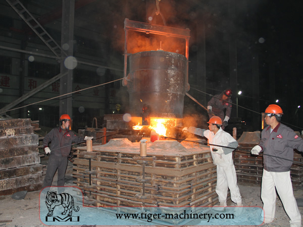
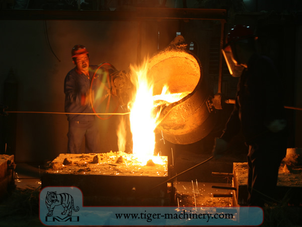
Po uformowaniu formy o odpowiedniej wilgotności, skrzynia z formą piaskową jest ustawiana do zalania ciekłym metalem – zazwyczaj żelazem, stalą, brązem, mosiądzem, aluminium, stopami magnezu lub różnymi stopami metali nieszlachetnych, które często zawierają ołów, cynę i cynk. Po zalaniu ciekłym metalem skrzynia jest odkładana do czasu, aż metal wystarczająco ostygnie, by być wytrzymałym. Następnie piasek jest usuwany, odsłaniając surowy odlew, który w przypadku żelaza lub stali może jeszcze żarzyć się na czerwono. Podczas odlewania metalami takimi jak żelazo czy ołów, które są znacznie cięższe od piasku formierskiego, skrzynia formierska jest często przykrywana ciężką płytą, aby zapobiec problemowi zwanemu unoszeniem formy. Unoszenie formy występuje, gdy ciśnienie metalu wypycha piasek ponad wnęką formy, powodując deformację i nieudany odlew.
Po odlaniu, rdzenie są rozbijane prętami lub śrutem i usuwane z odlewu. Metal z wlewu i nadlewów jest odcinany od surowego odlewu. Mogą być stosowane różne obróbki cieplne w celu usunięcia naprężeń po początkowym chłodzeniu oraz zwiększenia twardości – w przypadku stali lub żeliwa poprzez hartowanie w wodzie lub oleju. Odlew może być dodatkowo wzmocniony przez obróbkę powierzchniową polegającą na śrutowaniu, która zwiększa odporność na pękanie rozciągające i wygładza chropowatą powierzchnię.
Wymagania projektowe odlewnictwa piaskowego
The part to be made and its pattern must be designed to accommodate each stage of the process, as it must be possible to remove the pattern without disturbing the molding sand and to have proper locations to receive and position the cores. A slight taper, known as draft, must be used on surfaces perpendicular to the parting line, in order to be able to remove the pattern from the mold. This requirement also applies to cores, as they must be removed from the core box in which they are formed. The sprue and risers must be arranged to allow a proper flow of metal and gasses within the mold in order to avoid an incomplete casting. Should a piece of core or mold become dislodged it may be embedded in the final casting, forming a sand pit, which may render the casting unusable. Gas pockets can cause internal voids. These may be immediately visible or may only be revealed after extensive machining has been performed. For critical applications, or where the cost of wasted effort is a factor, non-destructive testing methods may be applied before further work is performed.
Próżniowe odlewanie form
Vacuum molding (V-process) is a variation of the sand casting process for most ferrous and non-ferrous metals, in which unbonded sand is held in the flask with a vacuum. The pattern is specially vented so that a vacuum can be pulled through it. A heat-softened thin sheet (0.003 to 0.008 in (0.076 to 0.203 mm)) of plastic film is draped over the pattern and a vacuum is drawn (200 to 400 mmHg (27 to 53 kPa)). A special vacuum forming flask is placed over the plastic pattern and is filled with a free-flowing sand. The sand is vibrated to compact the sand and a sprue and pouring cup are formed in the cope. Another sheet of plastic is placed over the top of the sand in the flask and a vacuum is drawn through the special flask; this hardens and strengthens the unbonded sand. The vacuum is then released on the pattern and the cope is removed. The drag is made in the same way (without the sprue and pouring cup). Any cores are set in place and the mold is closed. The molten metal is poured while the cope and drag are still under a vacuum, because the plastic vaporizes but the vacuum keeps the shape of the sand while the metal solidifies. When the metal has solidified, the vacuum is turned off and the sand runs out freely, releasing the casting.
Proces V jest znany z tego, że nie wymaga pochylenia formy, ponieważ folia plastikowa ma pewien stopień smarowności i lekko się rozszerza po odessaniu powietrza w skrzynce formierskiej. Proces charakteryzuje się wysoką dokładnością wymiarową, z tolerancją ±0,010 cala na pierwszym calu i ±0,002 cala na każdym kolejnym. Możliwe są przekroje poprzeczne tak małe jak 0,090 cala (2,3 mm). Wykończenie powierzchni jest bardzo dobre, zazwyczaj między 150 a 125 rms. Inne zalety to brak wad związanych z wilgocią, brak kosztów spoiw, doskonała przepuszczalność piasku oraz brak toksycznych oparów ze spalania spoiw. Wreszcie, model nie ulega zużyciu, ponieważ piasek go nie dotyka. Główną wadą jest to, że proces jest wolniejszy niż tradycyjne odlewanie w piasku, dlatego nadaje się tylko do niskiej i średniej wielkości produkcji, około 10 do 15 000 sztuk rocznie. Jednak czyni go to idealnym do prac prototypowych, ponieważ model można łatwo modyfikować, gdyż jest wykonany z plastiku.
Kucie
Kucie jest jednym z najstarszych znanych procesów obróbki metali. Tradycyjnie kucie było wykonywane przez kowala za pomocą młota i kowadła, choć wprowadzenie energii wodnej do produkcji i obróbki żelaza w XII wieku sprawiło, że młot i kowadło stały się przestarzałe. Kuźnia ewoluowała na przestrzeni wieków, stając się obiektem z inżynieryjnymi procesami, sprzętem produkcyjnym, oprzyrządowaniem, surowcami i produktami, aby sprostać wymaganiom nowoczesnego przemysłu.
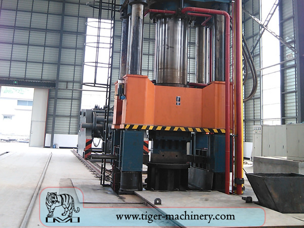
W dzisiejszych czasach kucie przemysłowe wykonuje się za pomocą pras lub młotów napędzanych sprężonym powietrzem, energią elektryczną, hydrauliką lub parą. Młoty te mogą mieć masy tłoków ważące tysiące funtów. Mniejsze młoty mechaniczne o masie tłoka 500 lb (230 kg) lub mniejszej oraz prasy hydrauliczne są również powszechne w kuźniach artystycznych. Niektóre młoty parowe są nadal używane, ale stały się przestarzałe wraz z dostępnością innych, wygodniejszych źródeł energii.
Zalety i wady kucia
Kucie może wytworzyć element, który jest mocniejszy niż równoważna część odlewana lub obrabiana maszynowo. Gdy metal jest kształtowany podczas procesu kucia, jego wewnętrzne ziarno odkształca się, podążając za ogólnym kształtem części. W rezultacie ziarno jest ciągłe w całej części, co prowadzi do elementu o ulepszonych właściwościach wytrzymałościowych.
Niektóre metale mogą być kute na zimno, ale żelazo i stal są prawie zawsze kute na gorąco. Kucie na gorąco zapobiega utwardzaniu zgniotowemu, które wynikałoby z kucia na zimno, zwiększając trudność wykonania dodatkowej obróbki skrawaniem elementu. Ponadto, choć utwardzanie zgniotowe może być pożądane w niektórych przypadkach, inne metody utwardzania, takie jak obróbka cieplna, są zazwyczaj bardziej ekonomiczne i łatwiejsze do kontrolowania. Stopy podatne na utwardzanie wydzieleniowe, takie jak większość stopów aluminium i tytanu, mogą być kute na gorąco, a następnie utwardzane.
Produkcja kuźnicza wymaga znacznych nakładów kapitałowych na maszyny, oprzyrządowanie, obiekty i personel. W przypadku kucia na gorąco potrzebny jest piec wysokotemperaturowy (czasami nazywany kuźnią) do nagrzewania wlewków lub kęsów. Ze względu na masywność dużych młotów i pras kuźniczych oraz wytwarzanych przez nie części, a także zagrożenia związane z pracą z gorącym metalem, często wymagany jest specjalny budynek do pomieszczenia operacji. W przypadku kucia matrycowego należy zapewnić absorpcję wstrząsów i wibracji generowanych przez młot. Większość operacji kuźniczych wykorzystuje matryce do kształtowania metalu, które muszą być precyzyjnie obrobione i starannie poddane obróbce cieplnej, aby prawidłowo ukształtować przedmiot obrabiany oraz wytrzymać ogromne siły.
Procesy kucia
Dostępnych jest wiele różnych rodzajów procesów kucia, jednak można je podzielić na trzy główne kategorie.
Wydłużenie: długość wzrasta, przekrój poprzeczny maleje
Spęczenie: długość maleje, przekrój poprzeczny wzrasta
Ściskany w zamkniętych matrycach do kompresji: powoduje przepływ wielokierunkowy
Typowe procesy kucia obejmują: kucie walcowe, kucie obrotowe, kucie swobodne, kucie matrycowe, kucie prasowe, automatyczne kucie na gorąco oraz kucie spęczające.