Technologie de coulée
Nous pouvons offrir les pièces de coulée centrifuge, coulée au sable, coulée sous vide et forgeage avec un usinage de haute qualité pour des exigences strictes.
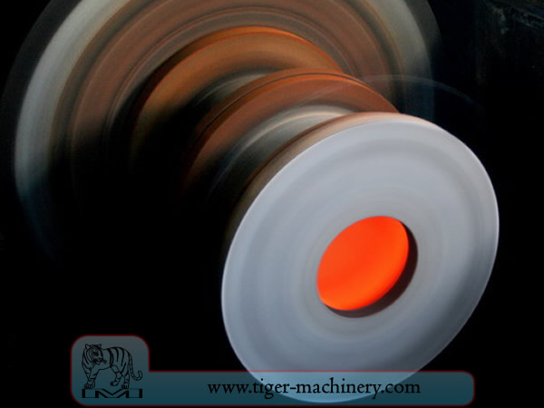
Moulage par centrifugation
In centrifugal casting, a permanent mold is rotated continuously about its axis at high speeds (300 to 3000 rpm) as the molten metal is poured. The molten metal is centrifugally thrown towards the inside mold wall, where it solidifies after cooling. The casting is usually a fine-grained casting with a very fine-grained outer diameter, owing to chilling against the mould surface. Impurities and inclusions are thrown to the surface of the inside diameter, which can be machined away. Casting machines may be either horizontal or vertical-axis. Horizontal axis machines are preferred for long, thin cylinders, vertical machines for rings. Most castings are solidified from the outside first. This may be used to encourage directional solidification of the casting, and thus give useful metallurgical properties to it. Often the inner and outer layers are discarded and only the intermediary columnar zone is used. Centrifugal casting was the invention of Alfred Krupp, who used it to manufacture cast steel tyres for railway wheels in 1852.
Caractéristiques de la coulée centrifuge
Les pièces moulées peuvent être fabriquées dans presque toutes les longueurs, épaisseurs et diamètres.
Différentes épaisseurs de paroi peuvent être produites à partir du même moule.
Élimine le besoin de noyaux.
Résistant à la corrosion atmosphérique, une situation typique avec les tuyaux.
Les propriétés mécaniques des pièces moulées par centrifugation sont excellentes.
Seules les formes cylindriques peuvent être produites avec ce procédé.
Les limites de taille sont jusqu'à 3 mètres (10 pieds) de diamètre et 15 mètres (50 pieds) de longueur.
Épaisseur de paroi de 2,5 mm à 125 mm (0,1 - 5,0 po).
Limite de tolérance : sur le diamètre extérieur peut être de 2,5 mm (0,1 po), sur le diamètre intérieur peut être de 3,8 mm (0,15 po).
La finition de surface varie de 2,5 mm à 12,5 mm (0,1 - 0,5 pouce) rms.
Avantages de la coulée centrifuge
Cylinders and shapes with rotational symmetry are most commonly cast by this technique. "Tall" castings (in the direction of the settling force acting, usually gravity) are always more difficult than short castings. In the centrifugal casting technique the radius of the rotation, along which the centrifugal force acts, replaces the vertical axis. The casting machine may be rotated to place this in any convenient orientation, relative to gravity's vertical. Horizontal and vertical axis machines are both used, simply to place the casting's longest dimension conveniently horizontal. Thin-walled cylinders are difficult to cast by other means, but centrifugal casting is particularly suited to them. To the rotation radius, these are effectively shallow flat castings and are thus simple. Centrifugal casting is also applied to the casting of disk and cylindrical shaped objects such as railway carriage wheels or machine fittings where the grain, flow, and balance are important to the durability and utility of the finished product. Providing that the shape is relatively constant in radius, noncircular shapes may also be cast.
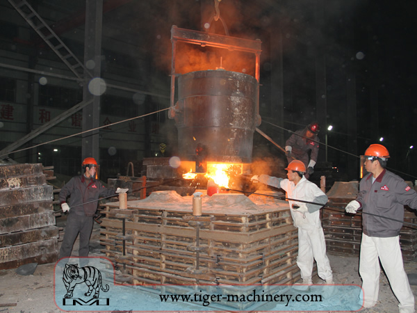
Moulage au sable
Le moulage au sable, également connu sous le nom de coulée en sable, est un procédé de fonderie caractérisé par l'utilisation du sable comme matériau de moule. Le terme moulage au sable peut également désigner un objet produit via ce procédé. Les pièces moulées au sable sont fabriquées dans des usines spécialisées appelées fonderies. Plus de 70 % de toutes les pièces moulées en métal sont produites via un procédé de moulage au sable.
Le moulage au sable est relativement peu coûteux et suffisamment réfractaire même pour une utilisation en fonderie d'acier. En plus du sable, un liant approprié (généralement de l'argile) est mélangé ou se trouve avec le sable. Le mélange est humidifié, typiquement avec de l'eau, mais parfois avec d'autres substances, pour développer la résistance et la plasticité de l'argile et rendre l'agrégat adapté au moulage. Le sable est généralement contenu dans un système de cadres ou de boîtes de moulage appelé châssis. Les cavités du moule et le système de coulée sont créés en compactant le sable autour de modèles, ou de patrons, ou en sculptant directement dans le sable.
Modèles de moulage au sable
From the design, provided by an engineer or designer, a skilled pattern maker builds a pattern of the object to be produced, using wood, metal, or a plastic such as expanded polystyrene. Sand can be ground, swept or strickled into shape. The metal to be cast will contract during solidification, and this may be non-uniform due to uneven cooling. Therefore, the pattern must be slightly larger than the finished product, a difference known as contraction allowance. Pattern-makers are able to produce suitable patterns using Contraction rules (these are sometimes called shrink allowance rulers where the ruled markings are deliberately made to a larger spacing according to the percentage of extra length needed). Different scaled rules are used for different metals, because each metal and alloy contracts by an amount distinct from all others. Patterns also have core prints that create registers within the molds into which are placed sand cores. Such cores, sometimes reinforced by wires, are used to create under-cut profiles and cavities which cannot be molded with the cope and drag, such as the interior passages of valves or cooling passages in engine blocks.
Les chemins d'entrée du métal dans la cavité du moule constituent le système de coulée et comprennent la descente de coulée, divers alimentateurs qui maintiennent une bonne 'alimentation' en métal, et les attaques de coulée qui relient le système de coulée à la cavité de moulage. Les gaz et la vapeur générés lors de la coulée sortent à travers le sable perméable ou via des masselottes, qui sont ajoutées soit dans le modèle lui-même, soit en pièces séparées.
Moule et matériaux de coulée au sable
A multi-part molding box (known as a casting flask, the top and bottom halves of which are known respectively as the cope and drag) is prepared to receive the pattern. Molding boxes are made in segments that may be latched to each other and to end closures. For a simple object—flat on one side—the lower portion of the box, closed at the bottom, will be filled with a molding sand. The sand is packed in through a vibratory process called ramming, and in this case, periodically screeded level. The surface of the sand may then be stabilized with a sizing compound. The pattern is placed on the sand and another molding box segment is added. Additional sand is rammed over and around the pattern. Finally a cover is placed on the box and it is turned and unlatched, so that the halves of the mold may be parted and the pattern with its sprue and vent patterns removed. Additional sizing may be added and any defects introduced by the removal of the pattern are corrected. The box is closed again. This forms a green mold which must be dried to receive the hot metal. If the mold is not sufficiently dried a steam explosion can occur that can throw molten metal about. In some cases, the sand may be oiled instead of moistened, which makes possible casting without waiting for the sand to dry. Sand may also be bonded by chemical binders, such as furane resins or amine-hardened resins.
Les refroidissements de la coulée en sable
Pour contrôler la structure de solidification du métal, il est possible de placer des plaques métalliques, des refroidisseurs, dans le moule. Le refroidissement local rapide associé formera une structure à grains plus fins et pourra former un métal légèrement plus dur à ces endroits. Dans les pièces moulées ferreuses, l'effet est similaire à la trempe des métaux dans le forgeage. Le diamètre intérieur d'un cylindre de moteur est durci par un noyau de refroidissement. Dans d'autres métaux, les refroidisseurs peuvent être utilisés pour favoriser la solidification directionnelle de la coulée. En contrôlant la façon dont une coulée gèle, il est possible d'empêcher les vides internes ou la porosité à l'intérieur des pièces moulées.
Noyaux de moulage au sable
Pour produire des cavités dans la pièce coulée—comme pour le refroidissement liquide dans les blocs moteurs et les culasses—des formes négatives sont utilisées pour réaliser des noyaux. Généralement moulés en sable, les noyaux sont insérés dans le moule après le retrait du modèle. Dans la mesure du possible, les conceptions évitent l'utilisation de noyaux en raison du temps de montage supplémentaire et donc du coût plus élevé.
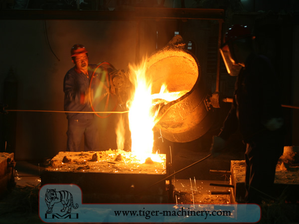
Une fois le moule terminé avec une teneur en humidité appropriée, le bac contenant le moule en sable est positionné pour être rempli de métal en fusion — généralement du fer, de l'acier, du bronze, du laiton, de l'aluminium, des alliages de magnésium ou divers alliages de métaux communs, qui incluent souvent du plomb, de l'étain et du zinc. Après le remplissage avec le métal liquide, le bac est mis de côté jusqu'à ce que le métal soit suffisamment refroidi pour être solide. Le sable est ensuite retiré, révélant une pièce brute qui, dans le cas du fer ou de l'acier, peut encore rougeoyer. Lors de la coulée avec des métaux comme le fer ou le plomb, qui sont nettement plus lourds que le sable de moulage, le châssis de coulée est souvent recouvert d'une plaque lourde pour éviter un problème appelé flottement du moule. Le flottement du moule se produit lorsque la pression du métal pousse le sable au-dessus de la cavité du moule hors de forme, entraînant l'échec de la coulée.
Après la coulée, les noyaux sont brisés par des tiges ou des billes et retirés de la pièce coulée. Le métal provenant de la carotte et des masselottes est coupé de la pièce brute. Divers traitements thermiques peuvent être appliqués pour soulager les contraintes du refroidissement initial et augmenter la dureté—dans le cas de l'acier ou de la fonte, par trempe dans l'eau ou l'huile. La pièce coulée peut être renforcée davantage par un traitement de compression de surface—comme le grenaillage de précontrainte—qui ajoute une résistance à la fissuration par traction et lisse la surface rugueuse.
Exigences de conception du moulage au sable
The part to be made and its pattern must be designed to accommodate each stage of the process, as it must be possible to remove the pattern without disturbing the molding sand and to have proper locations to receive and position the cores. A slight taper, known as draft, must be used on surfaces perpendicular to the parting line, in order to be able to remove the pattern from the mold. This requirement also applies to cores, as they must be removed from the core box in which they are formed. The sprue and risers must be arranged to allow a proper flow of metal and gasses within the mold in order to avoid an incomplete casting. Should a piece of core or mold become dislodged it may be embedded in the final casting, forming a sand pit, which may render the casting unusable. Gas pockets can cause internal voids. These may be immediately visible or may only be revealed after extensive machining has been performed. For critical applications, or where the cost of wasted effort is a factor, non-destructive testing methods may be applied before further work is performed.
Moulage sous vide
Vacuum molding (V-process) is a variation of the sand casting process for most ferrous and non-ferrous metals, in which unbonded sand is held in the flask with a vacuum. The pattern is specially vented so that a vacuum can be pulled through it. A heat-softened thin sheet (0.003 to 0.008 in (0.076 to 0.203 mm)) of plastic film is draped over the pattern and a vacuum is drawn (200 to 400 mmHg (27 to 53 kPa)). A special vacuum forming flask is placed over the plastic pattern and is filled with a free-flowing sand. The sand is vibrated to compact the sand and a sprue and pouring cup are formed in the cope. Another sheet of plastic is placed over the top of the sand in the flask and a vacuum is drawn through the special flask; this hardens and strengthens the unbonded sand. The vacuum is then released on the pattern and the cope is removed. The drag is made in the same way (without the sprue and pouring cup). Any cores are set in place and the mold is closed. The molten metal is poured while the cope and drag are still under a vacuum, because the plastic vaporizes but the vacuum keeps the shape of the sand while the metal solidifies. When the metal has solidified, the vacuum is turned off and the sand runs out freely, releasing the casting.
Le procédé V est connu pour ne pas nécessiter de dépouille car le film plastique possède un certain degré de lubrifiant et se dilate légèrement lorsque le vide est appliqué dans le châssis. Le procédé offre une grande précision dimensionnelle, avec une tolérance de ±0,010 in pour le premier pouce et de ±0,002 in par la suite. Des sections aussi petites que 0,090 in (2,3 mm) sont possibles. L'état de surface est très bon, généralement entre 150 et 125 rms. Les autres avantages incluent l'absence de défauts liés à l'humidité, aucun coût pour les liants, une excellente perméabilité du sable et l'absence de fumées toxiques provenant de la combustion des liants. Enfin, le modèle ne s'use pas car le sable ne le touche pas. Le principal inconvénient est que le procédé est plus lent que le moulage au sable traditionnel, il ne convient donc qu'à des volumes de production faibles à moyens, environ 10 à 15 000 pièces par an. Cependant, cela le rend parfait pour les travaux de prototypage, car le modèle peut être facilement modifié puisqu'il est en plastique.
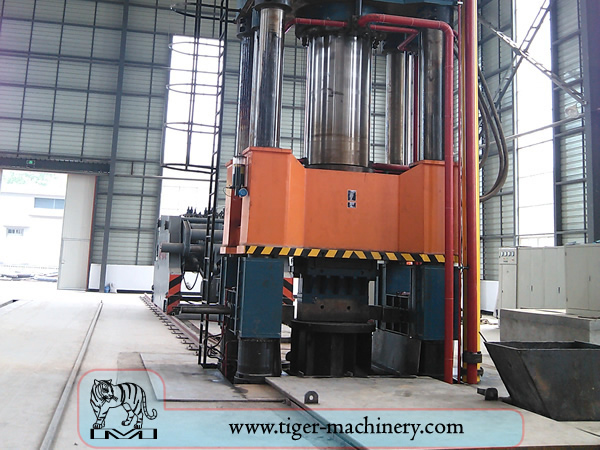
Forging
Le forgeage est l'un des plus anciens procédés de travail des métaux connus. Traditionnellement, le forgeage était réalisé par un forgeron utilisant un marteau et une enclume, bien que l'introduction de l'énergie hydraulique dans la production et le travail du fer au XIIe siècle ait rendu le marteau et l'enclume obsolètes. La forge a évolué au fil des siècles pour devenir une installation dotée de processus techniques, d'équipements de production, d'outillage, de matières premières et de produits répondant aux exigences de l'industrie moderne.
À l'époque moderne, le forgeage industriel s'effectue soit avec des presses, soit avec des marteaux actionnés par air comprimé, électricité, hydraulique ou vapeur. Ces marteaux peuvent avoir des masses alternatives de plusieurs milliers de livres. Des marteaux-pilons plus petits, d'une masse alternative de 500 lb (230 kg) ou moins, ainsi que des presses hydrauliques, sont également courants dans les forges d'art. Certains marteaux à vapeur restent en service, mais ils sont devenus obsolètes avec la disponibilité d'autres sources d'énergie plus pratiques.
Avantages et inconvénients du forgeage
Le forgeage peut produire une pièce plus résistante qu'une pièce coulée ou usinée équivalente. Lorsque le métal est formé pendant le processus de forgeage, son grain interne se déforme pour suivre la forme générale de la pièce. En conséquence, le grain est continu dans toute la pièce, ce qui donne une pièce aux caractéristiques de résistance améliorées.
Certains métaux peuvent être forgés à froid, mais le fer et l'acier sont presque toujours forgés à chaud. Le forgeage à chaud empêche l'écrouissage qui résulterait du forgeage à froid, ce qui augmenterait la difficulté d'effectuer des opérations d'usinage secondaires sur la pièce. De plus, bien que l'écrouissage puisse être souhaitable dans certaines circonstances, d'autres méthodes de durcissement de la pièce, comme le traitement thermique, sont généralement plus économiques et plus contrôlables. Les alliages susceptibles de durcissement par précipitation, comme la plupart des alliages d'aluminium et le titane, peuvent être forgés à chaud, puis durcis.
La forge de production implique des dépenses d'investissement importantes pour les machines, l'outillage, les installations et le personnel. Dans le cas du forgeage à chaud, un four à haute température (parfois appelé forge) est nécessaire pour chauffer les lingots ou les billettes. En raison de la massivité des grands marteaux et presses de forgeage et des pièces qu'ils peuvent produire, ainsi que des dangers inhérents au travail du métal chaud, un bâtiment spécial est souvent nécessaire pour abriter l'opération. Dans le cas des opérations de forgeage par estampage, des dispositions doivent être prises pour absorber les chocs et les vibrations générés par le marteau. La plupart des opérations de forgeage utilisent des matrices de formage des métaux, qui doivent être usinées avec précision et traitées thermiquement avec soin pour façonner correctement la pièce, ainsi que pour résister aux forces énormes impliquées.
Procédés de forgeage
Il existe de nombreux types de procédés de forgeage disponibles, mais ils peuvent être regroupés en trois catégories principales :
Drawn out : la longueur augmente, la section transversale diminue
Bouder : la longueur diminue, la section transversale augmente
Comprimé dans des matrices de compression fermées : produit un écoulement multidirectionnel
Les procédés de forgeage courants comprennent : le forgeage par laminage, le martelage, le cinglage, le forgeage libre, le forgeage en matrice, le forgeage sous presse, le forgeage à chaud automatique et le refoulement.