Gusstechnologie
Wir können Teile mit Zentrifugalguss, Sandguss, Vakuumformguss und Schmiedetechnologie anbieten, die für strenge Anforderungen gut und fein bearbeitet sind.
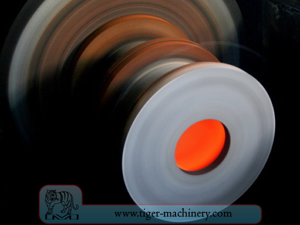
Zentrifugalguss
In centrifugal casting, a permanent mold is rotated continuously about its axis at high speeds (300 to 3000 rpm) as the molten metal is poured. The molten metal is centrifugally thrown towards the inside mold wall, where it solidifies after cooling. The casting is usually a fine-grained casting with a very fine-grained outer diameter, owing to chilling against the mould surface. Impurities and inclusions are thrown to the surface of the inside diameter, which can be machined away. Casting machines may be either horizontal or vertical-axis. Horizontal axis machines are preferred for long, thin cylinders, vertical machines for rings. Most castings are solidified from the outside first. This may be used to encourage directional solidification of the casting, and thus give useful metallurgical properties to it. Often the inner and outer layers are discarded and only the intermediary columnar zone is used. Centrifugal casting was the invention of Alfred Krupp, who used it to manufacture cast steel tyres for railway wheels in 1852.
Merkmale des Schleudergusses
Gussteile können in nahezu jeder Länge, Dicke und jedem Durchmesser hergestellt werden.
Unterschiedliche Wandstärken können mit derselben Formgröße hergestellt werden.
Entfernt die Notwendigkeit für Kerne.
Beständig gegen atmosphärische Korrosion, eine typische Situation bei Rohren.
Die mechanischen Eigenschaften von Schleuderguss sind ausgezeichnet.
Mit diesem Verfahren können nur zylindrische Formen hergestellt werden.
Größenbeschränkungen betragen bis zu 3 m (10 Fuß) Durchmesser und 15 m (50 Fuß) Länge.
Wandstärkenbereich von 2,5 mm bis 125 mm (0,1 - 5,0 Zoll).
Toleranzgrenze: am Außendurchmesser kann sie 2,5 mm (0,1 Zoll) betragen, am Innendurchmesser kann sie 3,8 mm (0,15 Zoll) betragen.
Oberflächenbeschaffenheit reicht von 2,5 mm bis 12,5 mm (0,1 - 0,5 Zoll) rms.
Vorteile des Schleudergusses
Cylinders and shapes with rotational symmetry are most commonly cast by this technique. "Tall" castings (in the direction of the settling force acting, usually gravity) are always more difficult than short castings. In the centrifugal casting technique the radius of the rotation, along which the centrifugal force acts, replaces the vertical axis. The casting machine may be rotated to place this in any convenient orientation, relative to gravity's vertical. Horizontal and vertical axis machines are both used, simply to place the casting's longest dimension conveniently horizontal. Thin-walled cylinders are difficult to cast by other means, but centrifugal casting is particularly suited to them. To the rotation radius, these are effectively shallow flat castings and are thus simple. Centrifugal casting is also applied to the casting of disk and cylindrical shaped objects such as railway carriage wheels or machine fittings where the grain, flow, and balance are important to the durability and utility of the finished product. Providing that the shape is relatively constant in radius, noncircular shapes may also be cast.
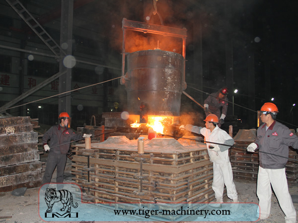
Sandguss
Sandguss, auch bekannt als Sandformguss, ist ein Metallgussverfahren, das durch die Verwendung von Sand als Formmaterial gekennzeichnet ist. Der Begriff Sandguss kann sich auch auf ein Objekt beziehen, das durch das Sandgussverfahren hergestellt wird. Sandgussteile werden in spezialisierten Fabriken, den Gießereien, produziert. Über 70 % aller Metallgussteile werden durch ein Sandgussverfahren hergestellt.
Sandguss ist relativ günstig und ausreichend feuerfest, selbst für den Einsatz in Stahlgießereien. Zusätzlich zum Sand wird ein geeignetes Bindemittel (normalerweise Ton) gemischt oder kommt mit dem Sand vor. Die Mischung wird üblicherweise mit Wasser, manchmal aber auch mit anderen Substanzen angefeuchtet, um die Festigkeit und Plastizität des Tons zu entwickeln und das Aggregat für die Formgebung geeignet zu machen. Der Sand ist typischerweise in einem System von Rahmen oder Formkästen enthalten, das als Formkasten bekannt ist. Die Formhohlräume und das Angusssystem werden erzeugt, indem der Sand um Modelle oder Muster verdichtet oder direkt in den Sand geschnitten wird.
Muster des Sandgusses
From the design, provided by an engineer or designer, a skilled pattern maker builds a pattern of the object to be produced, using wood, metal, or a plastic such as expanded polystyrene. Sand can be ground, swept or strickled into shape. The metal to be cast will contract during solidification, and this may be non-uniform due to uneven cooling. Therefore, the pattern must be slightly larger than the finished product, a difference known as contraction allowance. Pattern-makers are able to produce suitable patterns using Contraction rules (these are sometimes called shrink allowance rulers where the ruled markings are deliberately made to a larger spacing according to the percentage of extra length needed). Different scaled rules are used for different metals, because each metal and alloy contracts by an amount distinct from all others. Patterns also have core prints that create registers within the molds into which are placed sand cores. Such cores, sometimes reinforced by wires, are used to create under-cut profiles and cavities which cannot be molded with the cope and drag, such as the interior passages of valves or cooling passages in engine blocks.
Die Wege für den Eintritt von Metall in den Formhohlraum bilden das Angusssystem und umfassen den Einguss, verschiedene Speiser, die eine gute Metallzufuhr aufrechterhalten, sowie Eingusskanäle, die das Angusssystem mit dem Gusshohlraum verbinden. Während des Gusses entstehende Gase und Dampf entweichen durch den durchlässigen Sand oder über Steiger, die entweder im Modell selbst oder als separate Teile hinzugefügt werden.
Formkasten und Materialien des Sandgusses
A multi-part molding box (known as a casting flask, the top and bottom halves of which are known respectively as the cope and drag) is prepared to receive the pattern. Molding boxes are made in segments that may be latched to each other and to end closures. For a simple object—flat on one side—the lower portion of the box, closed at the bottom, will be filled with a molding sand. The sand is packed in through a vibratory process called ramming, and in this case, periodically screeded level. The surface of the sand may then be stabilized with a sizing compound. The pattern is placed on the sand and another molding box segment is added. Additional sand is rammed over and around the pattern. Finally a cover is placed on the box and it is turned and unlatched, so that the halves of the mold may be parted and the pattern with its sprue and vent patterns removed. Additional sizing may be added and any defects introduced by the removal of the pattern are corrected. The box is closed again. This forms a green mold which must be dried to receive the hot metal. If the mold is not sufficiently dried a steam explosion can occur that can throw molten metal about. In some cases, the sand may be oiled instead of moistened, which makes possible casting without waiting for the sand to dry. Sand may also be bonded by chemical binders, such as furane resins or amine-hardened resins.
Kühlrippen des Sandgusses
Um die Erstarrungsstruktur des Metalls zu kontrollieren, ist es möglich, Metallplatten, sogenannte Kühlplatten, in der Form zu platzieren. Die damit verbundene schnelle lokale Kühlung erzeugt eine feinkörnigere Struktur und kann an diesen Stellen ein etwas härteres Metall bilden. Bei Eisenlegierungsgussstücken ähnelt die Wirkung dem Abschrecken von Metallen in der Schmiedearbeit. Der Innendurchmesser eines Motorzylinders wird durch einen Kühlkern gehärtet. Bei anderen Metallen können Kühlplatten verwendet werden, um die gerichtete Erstarrung des Gussstücks zu fördern. Durch die Kontrolle der Art und Weise, wie ein Gussstück erstarrt, ist es möglich, innere Hohlräume oder Porosität im Inneren von Gussstücken zu verhindern.
Kerne des Sandgusses
Um Hohlräume im Guss zu erzeugen – wie zur Flüssigkeitskühlung in Motorblöcken und Zylinderköpfen – werden negative Formen zur Herstellung von Kernen verwendet. In der Regel sandgeformte Kerne werden nach dem Entfernen des Modells in die Gussform eingesetzt. Wann immer möglich, werden Konstruktionen vermieden, die Kerne erfordern, aufgrund der zusätzlichen Rüstzeit und damit höheren Kosten.
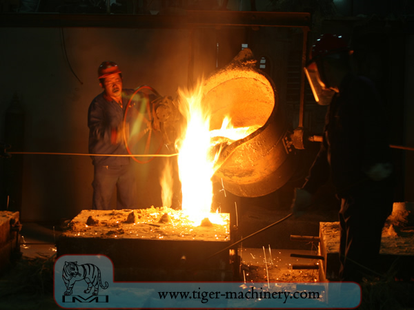
Mit einer fertigen Form bei geeignetem Feuchtigkeitsgehalt wird der Kasten mit der Sandform positioniert, um mit geschmolzenem Metall gefüllt zu werden – typischerweise Eisen, Stahl, Bronze, Messing, Aluminium, Magnesiumlegierungen oder verschiedene Pot-Metall-Legierungen, die oft Blei, Zinn und Zink enthalten. Nach dem Befüllen mit flüssigem Metall wird der Kasten beiseitegestellt, bis das Metall ausreichend abgekühlt und fest ist. Der Sand wird dann entfernt, wodurch ein rauer Guss freigelegt wird, der bei Eisen oder Stahl noch rot glühen kann. Beim Gießen mit Metallen wie Eisen oder Blei, die deutlich schwerer als der Gießsand sind, wird der Gießkasten oft mit einer schweren Platte abgedeckt, um ein Problem namens Formaufschwimmen zu verhindern. Formaufschwimmen tritt auf, wenn der Metalldruck den Sand über dem Formhohlraum verformt, was zum Fehlguss führt.
Nach dem Gießen werden die Kerne mit Stangen oder Schrot aufgebrochen und aus dem Gussstück entfernt. Das Metall vom Anguss und den Steigern wird vom Rohguss abgetrennt. Verschiedene Wärmebehandlungen können angewendet werden, um Spannungen aus der anfänglichen Abkühlung zu lösen und die Härte zu erhöhen – bei Stahl oder Eisen durch Abschrecken in Wasser oder Öl. Das Gussstück kann durch Oberflächendruckbehandlung – wie Kugelstrahlen – weiter verstärkt werden, was die Beständigkeit gegen Zugrisse erhöht und die raue Oberfläche glättet.
Designanforderungen des Sandgusses
The part to be made and its pattern must be designed to accommodate each stage of the process, as it must be possible to remove the pattern without disturbing the molding sand and to have proper locations to receive and position the cores. A slight taper, known as draft, must be used on surfaces perpendicular to the parting line, in order to be able to remove the pattern from the mold. This requirement also applies to cores, as they must be removed from the core box in which they are formed. The sprue and risers must be arranged to allow a proper flow of metal and gasses within the mold in order to avoid an incomplete casting. Should a piece of core or mold become dislodged it may be embedded in the final casting, forming a sand pit, which may render the casting unusable. Gas pockets can cause internal voids. These may be immediately visible or may only be revealed after extensive machining has been performed. For critical applications, or where the cost of wasted effort is a factor, non-destructive testing methods may be applied before further work is performed.
Vakuumformguss
Vacuum molding (V-process) is a variation of the sand casting process for most ferrous and non-ferrous metals, in which unbonded sand is held in the flask with a vacuum. The pattern is specially vented so that a vacuum can be pulled through it. A heat-softened thin sheet (0.003 to 0.008 in (0.076 to 0.203 mm)) of plastic film is draped over the pattern and a vacuum is drawn (200 to 400 mmHg (27 to 53 kPa)). A special vacuum forming flask is placed over the plastic pattern and is filled with a free-flowing sand. The sand is vibrated to compact the sand and a sprue and pouring cup are formed in the cope. Another sheet of plastic is placed over the top of the sand in the flask and a vacuum is drawn through the special flask; this hardens and strengthens the unbonded sand. The vacuum is then released on the pattern and the cope is removed. The drag is made in the same way (without the sprue and pouring cup). Any cores are set in place and the mold is closed. The molten metal is poured while the cope and drag are still under a vacuum, because the plastic vaporizes but the vacuum keeps the shape of the sand while the metal solidifies. When the metal has solidified, the vacuum is turned off and the sand runs out freely, releasing the casting.
Das V-Verfahren ist bekannt dafür, dass es keine Formschräge erfordert, da die Kunststofffolie eine gewisse Gleitfähigkeit besitzt und sich beim Evakuieren im Formkasten leicht ausdehnt. Das Verfahren weist eine hohe Maßgenauigkeit auf, mit einer Toleranz von ±0,010 Zoll für das erste Zoll und ±0,002 Zoll danach. Querschnitte von nur 0,090 Zoll (2,3 mm) sind möglich. Die Oberflächengüte ist sehr gut, normalerweise zwischen 150 und 125 rms. Weitere Vorteile sind keine feuchtigkeitsbedingten Fehler, keine Kosten für Bindemittel, ausgezeichnete Sanddurchlässigkeit und keine giftigen Dämpfe durch das Verbrennen der Bindemittel. Schließlich verschleißt das Modell nicht, da der Sand es nicht berührt. Der Hauptnachteil besteht darin, dass das Verfahren langsamer ist als traditionelles Sandgussverfahren, sodass es nur für niedrige bis mittlere Produktionsmengen geeignet ist; etwa 10 bis 15.000 Stück pro Jahr. Dies macht es jedoch perfekt für Prototypenarbeiten, da das Modell leicht modifiziert werden kann, da es aus Kunststoff besteht.
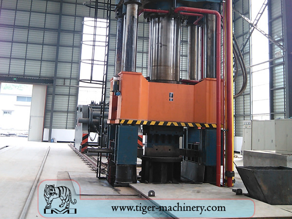
Forging
Schmieden ist einer der ältesten bekannten Metallbearbeitungsprozesse. Traditionell wurde Schmieden von einem Schmied mit Hammer und Amboss durchgeführt, obwohl die Einführung von Wasserkraft in die Produktion und Bearbeitung von Eisen im 12. Jahrhundert Hammer und Amboss veralten ließ. Die Schmiede hat sich über Jahrhunderte zu einer Einrichtung mit technischen Prozessen, Produktionsanlagen, Werkzeugen, Rohmaterialien und Produkten entwickelt, um den Anforderungen der modernen Industrie gerecht zu werden.
In der Neuzeit wird industrielles Schmieden entweder mit Pressen oder mit Hämmern durchgeführt, die von Druckluft, Elektrizität, Hydraulik oder Dampf angetrieben werden. Diese Hämmer können oszillierende Gewichte von mehreren tausend Pfund haben. Kleinere Maschinenhämmer mit einem oszillierenden Gewicht von 500 lb (230 kg) oder weniger sowie hydraulische Pressen sind auch in Kunstschmieden üblich. Einige Dampfhämmer sind noch in Gebrauch, aber sie wurden mit der Verfügbarkeit der anderen, bequemeren Energiequellen überflüssig.
Vorteile und Nachteile des Schmiedens
Schmieden kann ein Teil herstellen, das stärker ist als ein gleichwertiges Guss- oder bearbeitetes Teil. Während das Metall im Schmiedeprozess geformt wird, verformt sich sein inneres Korn, um der allgemeinen Form des Teils zu folgen. Dadurch ist das Korn durchgehend im Teil vorhanden, was zu einem Bauteil mit verbesserten Festigkeitseigenschaften führt.
Einige Metalle können kalt geschmiedet werden, aber Eisen und Stahl werden fast immer warm geschmiedet. Warmschmieden verhindert die Kaltverfestigung, die beim Kaltschmieden auftreten würde und die Durchführung sekundärer Bearbeitungsvorgänge am Werkstück erschweren würde. Auch wenn eine Kaltverfestigung in manchen Fällen wünschenswert sein mag, sind andere Methoden der Härtung des Werkstücks, wie z. B. die Wärmebehandlung, in der Regel wirtschaftlicher und besser kontrollierbar. Legierungen, die sich für eine Ausscheidungshärtung eignen, wie die meisten Aluminiumlegierungen und Titan, können warm geschmiedet und anschließend gehärtet werden.
Produktionsschmieden erfordert erhebliche Kapitalausgaben für Maschinen, Werkzeuge, Anlagen und Personal. Bei Warmschmieden ist ein Hochtemperaturofen (manchmal auch als Schmiedeofen bezeichnet) erforderlich, um Barren oder Knüppel zu erhitzen. Aufgrund der Massivität großer Schmiedehämmer und Pressen sowie der Teile, die sie herstellen können, und der Gefahren, die mit der Arbeit mit heißem Metall verbunden sind, ist häufig ein spezielles Gebäude erforderlich, um den Betrieb unterzubringen. Bei Gesenkschmiedevorgängen müssen Vorkehrungen getroffen werden, um die durch den Hammer erzeugten Stöße und Vibrationen zu absorbieren. Die meisten Schmiedevorgänge verwenden Metallumformwerkzeuge, die präzise bearbeitet und sorgfältig wärmebehandelt werden müssen, um das Werkstück korrekt zu formen und den enormen Kräften standzuhalten.
Schmiedeprozesse
Es gibt viele verschiedene Arten von Schmiedeverfahren, jedoch lassen sie sich in drei Hauptklassen einteilen.
Gezogen: Länge nimmt zu, Querschnitt nimmt ab
Stauchung: Länge nimmt ab, Querschnitt nimmt zu
In geschlossenen Pressmatrizen zusammengedrückt: erzeugt multidirektionalen Fluss
Übliche Schmiedeverfahren umfassen: Walzschmieden, Gesenkschmieden, Freiformschmieden, Prägeschmieden, Pressschmieden, automatisches Warmschmieden und Stauchen.