Tecnología de fundición
Podemos ofrecer piezas con tecnología de fundición centrífuga, fundición en arena, fundición por moldeo al vacío y forja, con mecanizados precisos y de calidad para requisitos estrictos.
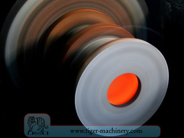
Centrifugal casting
In centrifugal casting, a permanent mold is rotated continuously about its axis at high speeds (300 to 3000 rpm) as the molten metal is poured. The molten metal is centrifugally thrown towards the inside mold wall, where it solidifies after cooling. The casting is usually a fine-grained casting with a very fine-grained outer diameter, owing to chilling against the mould surface. Impurities and inclusions are thrown to the surface of the inside diameter, which can be machined away. Casting machines may be either horizontal or vertical-axis. Horizontal axis machines are preferred for long, thin cylinders, vertical machines for rings. Most castings are solidified from the outside first. This may be used to encourage directional solidification of the casting, and thus give useful metallurgical properties to it. Often the inner and outer layers are discarded and only the intermediary columnar zone is used. Centrifugal casting was the invention of Alfred Krupp, who used it to manufacture cast steel tyres for railway wheels in 1852.
Características de la fundición centrífuga
Las piezas fundidas se pueden fabricar en casi cualquier longitud, espesor y diámetro.
Del mismo tamaño de molde se pueden producir diferentes espesores de pared.
Elimina la necesidad de núcleos.
Resistente a la corrosión atmosférica, una situación típica con tuberías.
Las propiedades mecánicas de las piezas fundidas por centrifugación son excelentes.
Solo se pueden producir formas cilíndricas con este proceso.
Los límites de tamaño son de hasta 3 m (10 pies) de diámetro y 15 m (50 pies) de longitud.
El rango de espesor de pared es de 2.5 mm a 125 mm (0.1 - 5.0 pulgadas).
Tolerancia límite: en el diámetro exterior puede ser de 2,5 mm (0,1 pulgadas) y en el diámetro interior puede ser de 3,8 mm (0,15 pulgadas).
El acabado superficial varía de 2.5 mm a 12.5 mm (0.1 - 0.5 in) rms.
Ventajas de la fundición centrífuga
Cylinders and shapes with rotational symmetry are most commonly cast by this technique. "Tall" castings (in the direction of the settling force acting, usually gravity) are always more difficult than short castings. In the centrifugal casting technique the radius of the rotation, along which the centrifugal force acts, replaces the vertical axis. The casting machine may be rotated to place this in any convenient orientation, relative to gravity's vertical. Horizontal and vertical axis machines are both used, simply to place the casting's longest dimension conveniently horizontal. Thin-walled cylinders are difficult to cast by other means, but centrifugal casting is particularly suited to them. To the rotation radius, these are effectively shallow flat castings and are thus simple. Centrifugal casting is also applied to the casting of disk and cylindrical shaped objects such as railway carriage wheels or machine fittings where the grain, flow, and balance are important to the durability and utility of the finished product. Providing that the shape is relatively constant in radius, noncircular shapes may also be cast.
Sand casting
La fundición en arena, también conocida como moldeo en arena, es un proceso de fundición de metales caracterizado por el uso de arena como material del molde. El término fundición en arena también puede referirse a un objeto producido mediante el proceso de fundición en arena. Las piezas fundidas en arena se producen en fábricas especializadas llamadas fundiciones. Más del 70% de todas las piezas fundidas de metal se producen mediante un proceso de fundición en arena.
La fundición en arena es relativamente barata y suficientemente refractaria incluso para su uso en fundiciones de acero. Además de la arena, se mezcla o se encuentra con ella un agente aglutinante adecuado (generalmente arcilla). La mezcla se humedece, típicamente con agua, pero a veces con otras sustancias, para desarrollar la resistencia y plasticidad de la arcilla y hacer que el agregado sea adecuado para el moldeo. La arena se contiene típicamente en un sistema de marcos o cajas de moldeo conocido como frasco. Las cavidades del molde y el sistema de canales se crean compactando la arena alrededor de modelos o patrones, o tallando directamente en la arena.
Patrones de fundición en arena
From the design, provided by an engineer or designer, a skilled pattern maker builds a pattern of the object to be produced, using wood, metal, or a plastic such as expanded polystyrene. Sand can be ground, swept or strickled into shape. The metal to be cast will contract during solidification, and this may be non-uniform due to uneven cooling. Therefore, the pattern must be slightly larger than the finished product, a difference known as contraction allowance. Pattern-makers are able to produce suitable patterns using Contraction rules (these are sometimes called shrink allowance rulers where the ruled markings are deliberately made to a larger spacing according to the percentage of extra length needed). Different scaled rules are used for different metals, because each metal and alloy contracts by an amount distinct from all others. Patterns also have core prints that create registers within the molds into which are placed sand cores. Such cores, sometimes reinforced by wires, are used to create under-cut profiles and cavities which cannot be molded with the cope and drag, such as the interior passages of valves or cooling passages in engine blocks.
Las vías para la entrada de metal en la cavidad del molde constituyen el sistema de canales de alimentación e incluyen el bebedero, varios alimentadores que mantienen una buena "alimentación" de metal, y entradas que conectan el sistema de canales con la cavidad de fundición. El gas y el vapor generados durante la fundición salen a través de la arena permeable o mediante bebederos de subida, que se añaden ya sea en el propio modelo o como piezas separadas.
Molding box and materials of sand casting
A multi-part molding box (known as a casting flask, the top and bottom halves of which are known respectively as the cope and drag) is prepared to receive the pattern. Molding boxes are made in segments that may be latched to each other and to end closures. For a simple object—flat on one side—the lower portion of the box, closed at the bottom, will be filled with a molding sand. The sand is packed in through a vibratory process called ramming, and in this case, periodically screeded level. The surface of the sand may then be stabilized with a sizing compound. The pattern is placed on the sand and another molding box segment is added. Additional sand is rammed over and around the pattern. Finally a cover is placed on the box and it is turned and unlatched, so that the halves of the mold may be parted and the pattern with its sprue and vent patterns removed. Additional sizing may be added and any defects introduced by the removal of the pattern are corrected. The box is closed again. This forms a green mold which must be dried to receive the hot metal. If the mold is not sufficiently dried a steam explosion can occur that can throw molten metal about. In some cases, the sand may be oiled instead of moistened, which makes possible casting without waiting for the sand to dry. Sand may also be bonded by chemical binders, such as furane resins or amine-hardened resins.
Escalofríos de fundición en arena
Para controlar la estructura de solidificación del metal, es posible colocar placas metálicas, enfriadores, en el molde. El enfriamiento local rápido asociado formará una estructura de grano más fino y puede generar un metal algo más duro en esas ubicaciones. En las piezas fundidas ferrosas, el efecto es similar al temple de metales en la forja. El diámetro interior del cilindro de un motor se endurece mediante un núcleo de enfriamiento. En otros metales, los enfriadores pueden usarse para promover la solidificación direccional de la pieza fundida. Al controlar la forma en que se congela una pieza fundida, es posible prevenir vacíos internos o porosidad dentro de las piezas fundidas.
Núcleos de fundición en arena
Para producir cavidades dentro de la fundición, como para refrigeración líquida en bloques de motor y cabezas de cilindro, se utilizan formas negativas para fabricar núcleos. Generalmente moldeados en arena, los núcleos se insertan en la caja de fundición después de retirar el patrón. Siempre que sea posible, se diseñan piezas que eviten el uso de núcleos, debido al tiempo adicional de preparación y, por lo tanto, al mayor costo.
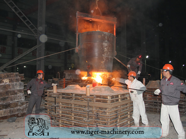
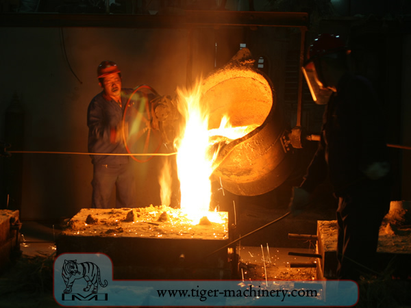
Con un molde completado con el contenido de humedad adecuado, la caja que contiene el molde de arena se coloca para ser llenada con metal fundido, típicamente hierro, acero, bronce, latón, aluminio, aleaciones de magnesio o varias aleaciones de metal pot metal, que a menudo incluyen plomo, estaño y zinc. Después de llenarlo con metal líquido, la caja se deja reposar hasta que el metal esté lo suficientemente frío para ser resistente. Luego se retira la arena, revelando una fundición rugosa que, en el caso del hierro o acero, aún puede estar brillando en rojo. Al fundir con metales como hierro o plomo, que son significativamente más pesados que la arena de fundición, el molde de fundición a menudo se cubre con una placa pesada para evitar un problema conocido como flotación del molde. La flotación del molde ocurre cuando la presión del metal empuja la arena sobre la cavidad del molde fuera de forma, causando que la fundición falle.
Después de la fundición, los machos se rompen con varillas o perdigones y se retiran de la pieza fundida. El metal del bebedero y los bebederos se corta de la pieza fundida en bruto. Se pueden aplicar varios tratamientos térmicos para aliviar las tensiones del enfriamiento inicial y agregar dureza—en el caso del acero o hierro, mediante temple en agua o aceite. La pieza fundida puede fortalecerse aún más mediante un tratamiento de compresión superficial—como el granallado—que agrega resistencia al agrietamiento por tracción y alisa la superficie rugosa.
Requisitos de diseño de la fundición en arena
The part to be made and its pattern must be designed to accommodate each stage of the process, as it must be possible to remove the pattern without disturbing the molding sand and to have proper locations to receive and position the cores. A slight taper, known as draft, must be used on surfaces perpendicular to the parting line, in order to be able to remove the pattern from the mold. This requirement also applies to cores, as they must be removed from the core box in which they are formed. The sprue and risers must be arranged to allow a proper flow of metal and gasses within the mold in order to avoid an incomplete casting. Should a piece of core or mold become dislodged it may be embedded in the final casting, forming a sand pit, which may render the casting unusable. Gas pockets can cause internal voids. These may be immediately visible or may only be revealed after extensive machining has been performed. For critical applications, or where the cost of wasted effort is a factor, non-destructive testing methods may be applied before further work is performed.
Moldeo por vacío
Vacuum molding (V-process) is a variation of the sand casting process for most ferrous and non-ferrous metals, in which unbonded sand is held in the flask with a vacuum. The pattern is specially vented so that a vacuum can be pulled through it. A heat-softened thin sheet (0.003 to 0.008 in (0.076 to 0.203 mm)) of plastic film is draped over the pattern and a vacuum is drawn (200 to 400 mmHg (27 to 53 kPa)). A special vacuum forming flask is placed over the plastic pattern and is filled with a free-flowing sand. The sand is vibrated to compact the sand and a sprue and pouring cup are formed in the cope. Another sheet of plastic is placed over the top of the sand in the flask and a vacuum is drawn through the special flask; this hardens and strengthens the unbonded sand. The vacuum is then released on the pattern and the cope is removed. The drag is made in the same way (without the sprue and pouring cup). Any cores are set in place and the mold is closed. The molten metal is poured while the cope and drag are still under a vacuum, because the plastic vaporizes but the vacuum keeps the shape of the sand while the metal solidifies. When the metal has solidified, the vacuum is turned off and the sand runs out freely, releasing the casting.
El proceso V es conocido por no requerir un cono de arrastre porque la película plástica tiene cierto grado de lubricidad y se expande ligeramente cuando se aplica vacío en el molde. El proceso tiene alta precisión dimensional, con una tolerancia de ±0.010 pulgadas para la primera pulgada y ±0.002 pulgadas en adelante. Son posibles secciones transversales tan pequeñas como 0.090 pulgadas (2.3 mm). El acabado superficial es muy bueno, generalmente entre 150 y 125 rms. Otras ventajas incluyen la ausencia de defectos relacionados con la humedad, sin costo por aglutinantes, excelente permeabilidad de la arena y sin humos tóxicos por la quema de aglutinantes. Finalmente, el modelo no se desgasta porque la arena no lo toca. La principal desventaja es que el proceso es más lento que la fundición en arena tradicional, por lo que solo es adecuado para volúmenes de producción bajos a medios; aproximadamente de 10 a 15,000 piezas al año. Sin embargo, esto lo hace perfecto para trabajos de prototipos, ya que el modelo se puede modificar fácilmente al estar hecho de plástico.
Forging
La forja es uno de los procesos de metalistería más antiguos conocidos. Tradicionalmente, la forja era realizada por un herrero usando martillo y yunque, aunque la introducción de la energía hidráulica en la producción y trabajo del hierro en el siglo XII llevó al martillo y el yunque a la obsolescencia. La herrería o fragua ha evolucionado a lo largo de los siglos para convertirse en una instalación con procesos diseñados, equipos de producción, herramientas, materias primas y productos para satisfacer las demandas de la industria moderna.
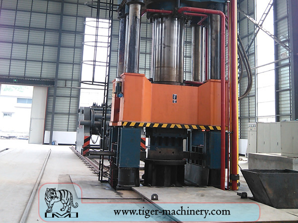
En la época moderna, la forja industrial se realiza ya sea con prensas o con martillos accionados por aire comprimido, electricidad, hidráulica o vapor. Estos martillos pueden tener pesos reciprocantes de miles de libras. Martillos de potencia más pequeños, con peso reciprocante de 500 lb (230 kg) o menos, y prensas hidráulicas también son comunes en las herrerías artísticas. Algunos martillos de vapor siguen en uso, pero se volvieron obsoletos con la disponibilidad de otras fuentes de energía más convenientes.
Ventajas y desventajas de la forja
La forja puede producir una pieza más resistente que una pieza equivalente fundida o mecanizada. A medida que el metal se moldea durante el proceso de forja, su grano interno se deforma para seguir la forma general de la pieza. Como resultado, el grano es continuo en toda la pieza, dando lugar a una pieza con características de resistencia mejoradas.
Algunos metales pueden forjarse en frío, pero el hierro y el acero casi siempre se forjan en caliente. El forjado en caliente evita el endurecimiento por deformación que resultaría del forjado en frío, lo que aumentaría la dificultad de realizar operaciones secundarias de mecanizado en la pieza. Además, aunque el endurecimiento por deformación pueda ser deseable en algunas circunstancias, otros métodos de endurecimiento de la pieza, como el tratamiento térmico, son generalmente más económicos y más controlables. Las aleaciones susceptibles al endurecimiento por precipitación, como la mayoría de las aleaciones de aluminio y el titanio, pueden forjarse en caliente, seguidas de un endurecimiento.
La forja de producción implica un gasto de capital significativo en maquinaria, herramientas, instalaciones y personal. En el caso de la forja en caliente, se requiere un horno de alta temperatura (a veces denominado fragua) para calentar lingotes o palanquillas. Debido a la masividad de los grandes martillos y prensas de forja y las piezas que pueden producir, así como a los peligros inherentes al trabajo con metal caliente, a menudo se necesita un edificio especial para albergar la operación. En el caso de las operaciones de forja por estampación, deben tomarse medidas para absorber el impacto y la vibración generados por el martillo. La mayoría de las operaciones de forja utilizan matrices de conformado de metal, que deben mecanizarse con precisión y tratarse térmicamente cuidadosamente para dar forma correcta a la pieza de trabajo, así como para soportar las enormes fuerzas involucradas.
Procesos de forja
Existen muchos tipos diferentes de procesos de forja disponibles, sin embargo, se pueden agrupar en tres clases principales:
Alargado: la longitud aumenta, la sección transversal disminuye
Upset: la longitud disminuye, la sección transversal aumenta
Comprimido en matrices de compresión cerrada: produce flujo multidireccional
Los procesos de forja comunes incluyen: forja por laminación, recalcado, forjado libre, forjado en estampa, forja por prensa, forja en caliente automática y recalcado.